4.3.2 Squeegee adjustment
wheels
• Put the machine in safe conditions.
• Remove the squeegee support (see sec-
tion 4.3.1 at page 23).
• Remove the squeegee adjustment
knob and the spring.
• Remove the Adjustment Wheel As-
sembly.
• Unscrew the fixing screw of the
wheel to the support.
• Proceed at reverse to refit the part.
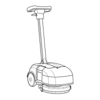
4.3.3 Squeegee Rotation Arm
• Put the machine in safe conditions.
• Disassemble the Squeegee Support
(see section 4.3.1 at page 23) (see fig. 4.3.3-15).
• Loose the screws that block the
Squeegee Rotation Arm to the Ma-
chine Chassis.
• Remove the Squeegee Rotation Arm.
• Proceed at reverse to refit the part
taking care about the bushing posi-
tioning.
4.3.3-15 4.3.3-16
4.3.4 Squeegee Actuator
• Put the machine in safe conditions.
• Remove the battery charger (see section
4.1.3 at page 22).
• Disconnect the chain from the plate
and the clip.
• Remove the actuator assembly by
unscrewing the fixing screws.
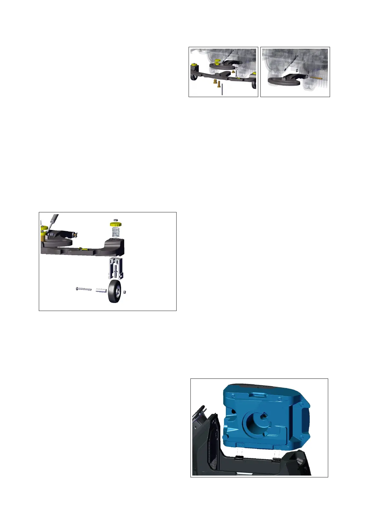
4.3.5 Recovery Tank
• Put the machine in safe conditions.
• Uncouple the Vacuum Hose and the
Drain Hose from the Recovery tank
Inlet.
• Remove the Vacuum Motor (see section
4.3.7 at page 25).
• After having provided a support, un-
screw the screws of the retaining
rope and of the tank rotation hinges
and remove it.
• Remove the internal components of
the tank.
24
 Loading...