5 Inputs HIMatrix
Page 26 of 72 HI 800 023 E Rev. 1.01
5 Inputs
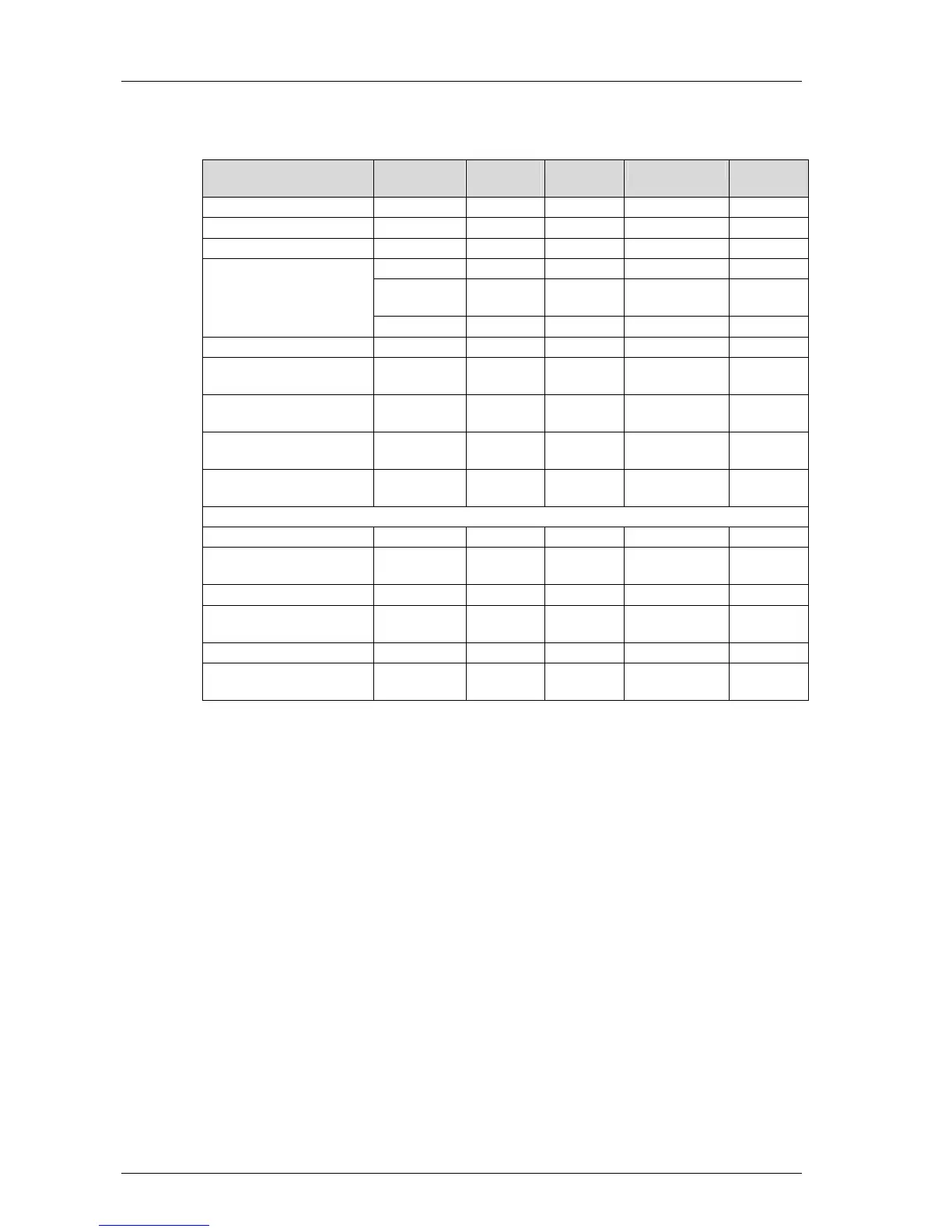
Overview of the HIMatrix system inputs:
Device Type
Number of
inputs
Safety-
related
Non-reactive
Electrically
isolated
F20 controller Digital 8 • • -
F30 controller Digital 20 • • -
F31 controller Digital 20 • • -
Digital 24 • • -
24-bit
counter
2 • • -
F35 controller
Analog 8 • • -
F1 DI 16 01 remote I/O Digital 16 • • -
F3 DIO 8/8 01 remote
I/O
Digital 8 • • -
F3 DIO 16/8 01 remote
I/O
Digital 16 • • -
F3 AIO 8/4 01 remote
I/O
Analog 8 • • -
F3 DIO 20/8 02 remote
I/O
Digital 20 • • -
F60 modular controller:
DIO 24/16 01 module Digital 24 • • •
DI 32 01 module (con-
figurable for line control)
Digital 32 • • •
DI 24 01 module (110 V) Digital 24 • • •
CIO 2/4 01 module
24-bit
counter
2 • • •
AI 8 01 module Analog 8 • • •
MI 24 01 module
Analog or
digital
24 • • •
Table 13: Overview of the HIMatrix System Inputs
5.1 General
Safety-related inputs can be used for both safety-related signals and non-safety-related
signals.
The controllers provide status and fault information as follows:
Through the diagnostic LEDs on the devices and modules.
Using system signals or system variables that the user program is able to evaluate.
Storing messages in the diagnostic memory that can be read by the PADT.
Safety-related input modules automatically perform stringent, cyclic self-tests during
operation. These test routines are TÜV tested and monitor the safe functioning of the
corresponding module.
If a fault occurs, the controller sends a low level to the user program and, if possible, issues
the fault information. The user program can read out the error code and evaluate this fault
information.
For a few number of component failures that do not affect safety, no diagnostic information
is provided.
 Loading...


