HIMatrix 5 Inputs
HI 800 023 E Rev. 1.01 Page 31 of 72
voltage is not reliable; with voltage inputs, the channels must be terminated with a 10 kΩ
resistor. The internal resistance of the source must be taken into account.
To measure currents, the shunt is connected in parallel to an input; in doing so the 10 kΩ
resistor is not required.
The inputs of the MI 24 01 module are only current inputs, because of the internal shunts,
and cannot be used as voltage inputs.
If input channels are not used, the measurement input must be connected to the reference
potential. Thus negative influences (fluctuating input voltages) on other channels in case of
an open-circuit are avoided.
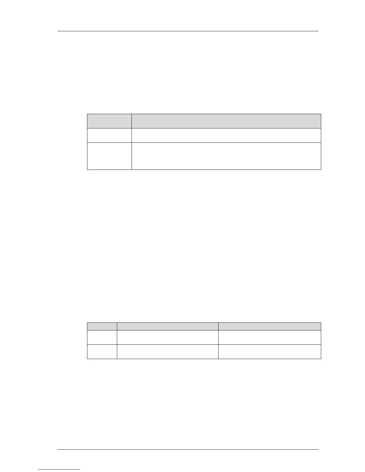
Operating sys-
tem version
Procedure
Versions be-
yond 7
It is sufficient not to assign unused inputs global variables.
Versions prior
to 7
For the unused input channel, set the corresponding signal AI[0x].Used to
the default value FALSE or 0 in ELOP II Hardware Management. In doing
so, the channel is masked out in the user program, i.e., no signals of this
channel are available within the logic.
Table 19: Configuration of Unused Inputs
5.4.2 Test Routines
The controller processes analog values in parallel via two multiplexers and two
analog/digital converters with 12-bit resolution and compares the results. Additionally, the
controller switches on test values via digital/analog converters, converts them back to
digital values and compares them with the default values.
When an error is detected, the controller sends 0 to the user program as input value for
further processing, and sets the error state.
5.4.3 Reaction in the Event of a Fault
If there are channel faults in the analog inputs, the error code of the corresponding channel
is set to a value > 0. If the entire module is faulty the error code for the module is set to a
value > 0.
In addition to the analog value, the user program must also evaluate the error code. For
values less than 0, a safety-related reaction must be planned.
A compact system activates the FAULT LED, a F60 module the ERR LED.
The error code allows the user to monitor the external wiring and program additional fault
reactions in the user program.
Version Access to the error code Error code name
Versions
beyond 7
In the ...Channels tab located in the
detail view of the module or device
->Error code [bytes] in the row with the
channel number
Versions
prior to 7
In the Signal Connections... window of
the module or device
AI[xx].error code, xx = channel number
Table 20: Error Codes with Analog Inputs
 Loading...


