HIMatrix 5 Inputs
HI 800 023 E Rev. 1.01 Page 29 of 72
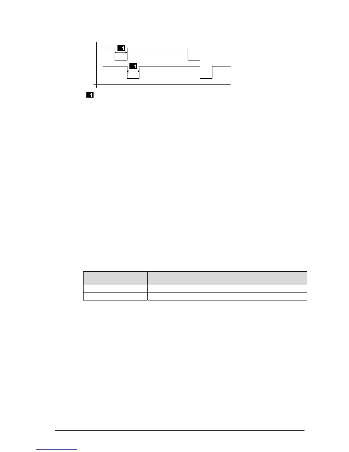
T 1
T 2
Configurable 5...2 000 µs
Figure 3: Pulsed Signal T1, T2
Line control detect the following faults:
Cross-circuit between two parallel lines,
Improper connections of two lines (e.g., TO 2 to DI 3),
Earth fault of a line (with earthed ground only),
Open-circuit or open contacts, i.e., including when one of the two EMERGENCY STOP
switches mentioned above has been engaged, the LED blinks and the error code is
created.
If such a fault occurs, the following reactions are triggered:
The FAULT LED on the module's or controller's front plate blinks.
The inputs are set to low level.
An (evaluable) error code is created.
5.4 Safety-Related Analog Inputs
(F35, F3 AIO 8/4 01 and F60)
5.4.1 General
The analog input channels convert the input signals into a value of type INTEGER. The
values are available to the user program as variables associated with the following system
variables or system signals :
Operating system ver-
sion
Value
Versions beyond 7 System variable -> Value [INT]
Versions prior to 7 System signal AI[xx].Value (xx = channel number).
Table 15: Value of Safety-Related Analog Inputs
The safety-related precision is the guaranteed accuracy of the analog input without module
fault reaction. This value must be taken into account when configuring the safety functions.
The value range for the inputs depend on the device or module:
 Loading...


