HIMatrix 9 Configuring Communication
HI 800 023 E Rev. 1.01 Page 61 of 72
i
If this condition is not met, the availability of a safeethernet connection can only be
guaranteed in a collision and fault-free network. However, this is not a safety problem for
the processor module!
i
Make sure that the communication system complies with the configured response time!
If this conditions cannot always be ensured, a corresponding connection system variable
for monitoring the response time is available. If the measured response time is not seldom
exceeded for over the half P2P ReceiveTMO, the configured response time must be
increased.
The receive timeout must be adjusted according to the new value configured for response
time.
NOTE
In the following examples, the formulas for calculating the worst case reaction time
only apply for a connection with HIMatrix controllers if the parameter
safety time = 2 * watchdog time
has been set in the systems.
9.2.3 Maximum Cycle Time of the HIMatrix Controller
To determine the maximum cycle time for a HIMatrix controller, HIMA recommends
proceeding as follows:
To determine the maximum cycle time for the HIMatrix controller
1. Use the system under the maximum load. In the process, all communication
connections must be operating both via safeethernet and standard protocols. Frequently
read the cycle time in the Control Panel and note the maximum cycle time.
2. Repeat step 1 for the next communication partner (i.e., the second HIMatrix controller).
3. The required maximum cycle time is the greater of the two time values ascertained.
The maximum cycle time was determined and is used in the following calculations.
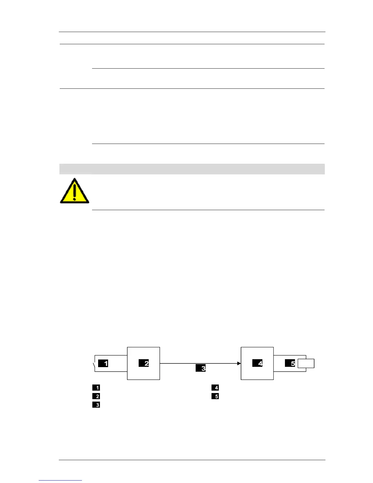
9.2.4 Calculating the Worst Case Reaction Time
The worst case reaction time T
R
is the time between a change on the sensor input signal of
PES 1 and a reaction on the corresponding output of PES 2. It is calculated as follows:
Input
HIMatrix Controller PES 1
Safety-Related Protocol
HIMatrix Controller PES 2
Output
Figure 4: Reaction Time with Interconnection of Two HIMatrix Controllers
 Loading...


