5 Inputs HIMatrix
Page 32 of 72 HI 800 023 E Rev. 1.01
5.5 Safety-Related Counters (F35 and F60)
Unless otherwise noted, the points previously mentioned apply for the CIO 2/4 01 counter
module of the F60 as well as for the counters of the F35.
5.5.1 General
A counter channel can be configured for operation as a high-speed up or down counter with
24-bit resolution or as a decoder in Gray code.
If used as high-speed up or down counters, the pulse input and count direction input signals
are required in the application. A reset only takes place in the user program.
The CIO 2/4 01 counter module of the F60 has 4-bit or 8-bit encoder resolution, whereas
the F35 has a 3-bit or 6-bit encoder resolution. A reset is possible.
The interconnection of two independent 4-bit inputs to an 8-bit input (example of F60) can
only be carried out via the user program. No switching option is planned for this purpose.
The encoder function monitors the change of the bit pattern on the input channels. The bit
patterns on the inputs are transferred directly to the user program. They are represented in
the PADT as decimal numbers corresponding to the bit pattern (Counter[0x].Value).
Depending on the application, this number (which corresponds to the Gray Code bit
pattern) can be converted into, for example, the corresponding decimal value.
5.5.2 Reaction in the Event of a Fault
If the test facilities detect a fault in the counter section of the device or module, they set a
status bit for evaluation in the user program. Additionally, the user program can also
consider the corresponding error code.
A compact system activates the ERROR LED, a F60 module the ERR LED.
The error code allows the user to monitor the external wiring and program additional fault
reactions in the user program.
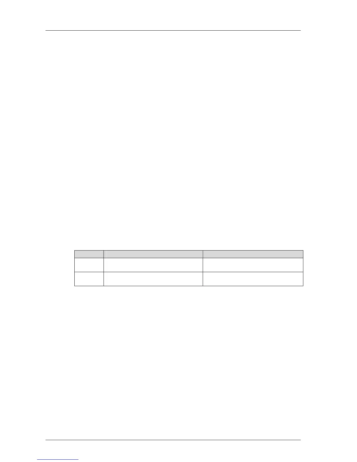
Version Access to the error code Error code name
Versions
beyond 7
In the ...Channels tab located in the
detail view of the module or device
->Error code [bytes] in the row with the
channel number
Versions
prior to 7
In the Signal Connections... window of
the module or device
Counter[xx].error code, xx = channel
number
Table 21: Error Codes with Counter Inputs
5.6 Checklist for Safety-Related Inputs
HIMA recommends using the following checklist for engineering, programming and starting
up safety-related inputs. It can be used for helping with planning as well as to demonstrate
later on that the planning phase was carefully completed.
When engineering or starting up the system, a checklist must be filled out for each of the
safety-related input channels used in the system to verify the requirements to be met. This
is the only way to ensure that all requirements were considered and clearly recorded. The
checklist also documents the relationship between the external wiring and the user
program.
The checklist HIMatrix_Checklist_Inputs.doc is available in Microsoft® Word® format. All
the checklists are contained in the ZIP file HIMatrix_Checklists.zip that can be downloaded
from the HIMA website www.hima.com.
 Loading...


