3.3 Connecting the Voltage Cords
47
3
Chapter 3 Connecting to Lines to be Measured
3
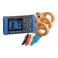
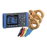
Connect the L9438-53 voltage cords to the instrument’s voltage input terminals while
checking the [WIR, DIAG] screen. The instrument ships with one each of the black,
red, yellow, and blue voltage cords and alligator clips as well as five spiral tubes.
Group the cords together with the spiral tubes as necessary.
See: "Bundle the Voltage Cord Leads with the Spiral Tubes" (p. 22)
Preparation items
3.3 Connecting the Voltage Cords
• To avoid electric shock and short-circuit accidents, use only the
specified L9438-53 Voltage Cord to connect the instrument volt-
age input terminals to the circuit to be tested.
• To ensure voltage cord integrity, grip cords by the plug when
connecting o
r disconnecting them.
Voltage cords used by wiring type
Measurement target Voltage cord to use (color)
Single-phase/2-wire (1P2W),
Single-phase/3-wire (1P3W1U)
Two cords (black and red)
Single-phase/3-wire (1P3W)
3-phase/3-wire (3P3W2M)
Three cords (black, red, and yellow)
3-phase/3-wire (3P3W3M) Three cords (red, yellow, and blue)
3-phase/4-wire (3P4W) Four cords (black, red, yellow, and blue)
Red
Blue
L9438-53 Voltage Cord
1 set
φ11 mm
Model 9804-02 Magnet Adapter
(optional, black, standard screws: M6 pan-head screw)
Black
Yellow
Model 9804-01 Magnet Adapter
(optional, red, standard screws: M6 pan-head screw)
 Loading...