3.4 Connecting a Clamp Sensors
49
3
Chapter 3 Connecting to Lines to be Measured
3
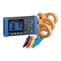
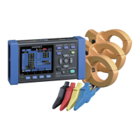
Connect the optional clamp sensors to the instrument’s current input terminals while
checking the [WIR, DIAG] screen. (Provide the required number of sensors accord-
ing to the line and connection type being measured.)
See the instruction manual supplied with the clamp sensor for specification details
and us
age procedures.
3.4 Connecting a Clamp Sensors
When disconnecting the BNC connector, be sure to release the
lock before pulling off the connector. Forcibly pulling the connector
without releasing the lock, or pulling on the cable, can damage the
connector.
Measurement target Clamp sensors (CH, spiral tube color)
Single-phase/2-wire
(1P2W)
one (CH1 red)
Single-phase/3-wire
(1
P3W
)
two (CH1 red, CH2 yellow)
3-phase/3-wire
(3P3W
2M)
two (CH1 red, CH2 yellow)
3-phase/3-wire
(3
P3W
3M)
three (CH1 red, CH2 yellow, CH3 blue)
3-phase/4-wire (3P4W) three (CH1 red, CH2 yellow, CH3 blue)
 Loading...