

T
Tanner LivingstonAug 2, 2025
What to do if Hioki Other power does not turn on?
- LLaurie KingAug 2, 2025
If the Hioki Other power does not turn on, the fuse may be blown. In this case, please contact your authorized Hioki distributor or reseller.
What to do if Hioki Other power does not turn on?
If the Hioki Other power does not turn on, the fuse may be blown. In this case, please contact your authorized Hioki distributor or reseller.
Details on registered trademarks and instrument model numbers.
Lists the standard package contents and available optional accessories.
Explanation of symbols used on the instrument and in the manual.
Defines measurement tolerances and electrical environment categories (CAT II-IV).
Covers preliminary checks, installation, and environmental considerations.
Provides guidelines for handling the instrument, clamp sensor, and cables.
Outlines the sequence of operations for measurement setup and connection.
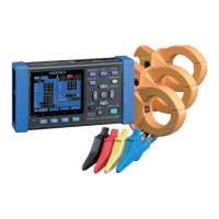
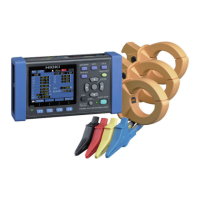
General description of the PW3360 Clamp on Power Logger.
Highlights key functionalities and capabilities of the instrument.
Identifies and describes the instrument's physical components and controls.
Explains the different screens and their layouts on the instrument.
Details the meaning of various icons and indicators displayed on the screen.
Provides a step-by-step procedure for preparing the instrument before measurement.
Covers essential setup steps after purchasing the instrument.
Outlines the necessary checks before operating the instrument.
Instructions for inserting, removing, and managing SD memory cards.
Details on powering the instrument using AC adapter or measurement lines.
Procedures for turning the instrument's power on and off.
Step-by-step guide for connecting the instrument to measurement lines.
How to configure measurement settings using the wiring diagram screen.
Instructions for connecting the voltage measurement cords.
Procedure for connecting the current clamp sensors.
Steps for connecting voltage cords to the actual measurement lines.
Steps for connecting clamp sensors to the actual measurement lines.
Guide to navigating and using the instrument's settings screen.
Details on how to modify measurement parameters like wiring and frequency.
Configuration options for saving measurement data, intervals, and items.
Adjusting system-level parameters like clock, language, and backlight.
Procedures for resetting the instrument to factory default settings.
Overview of the default values for all instrument settings.
How to use the main measurement screen for data viewing.
Describes the various measurement data screens available.
Displays voltage, current, power, and energy data in a list format.
Provides detailed RMS, fundamental, peak, and phase angle values.
Displays per-channel and total active, reactive, and apparent power.
Shows active energy (consumption/regeneration) and reactive energy.
Displays active power demand values over time in a graph format.
Visualizes harmonic levels, content percentage, and phase angles.
Presents harmonic data in a tabular list format.
Displays voltage and current waveforms, including RMS values and frequency.
Allows users to enlarge specific measured values on the display.
Displays selected measurement parameters over time as a trend graph.
Explains manual, time, interval, and repeat recording start options.
Procedures for initiating recording manually, by time, or by interval.
Methods for stopping recording manually or by specifying a time.
How to configure and use the repeat recording function.
Describes instrument behavior and data backup during power outages.
Lists settings that can be configured using the Quick Set function.
Describes how to apply normal settings in conjunction with Quick Set.
Guide to navigating the file screen for SD card and internal memory.
Details the file and folder organization on SD cards and internal memory.
Procedure for saving the current screen display as a BMP file.
Instructions for saving the instrument's current settings.
How to load previously saved settings files onto the instrument.
Procedure for transferring files from internal memory to an SD card.
Steps for deleting files and folders from storage media.
Guide to formatting SD memory cards and internal memory.
Instructions for ejecting the SD card and copying data to a computer.
Overview of the SF1001 software for data analysis.
Steps for opening and analyzing measurement data in Microsoft Excel.
Using software to automatically create Excel graphs from measurement data.
Procedure for copying data from the instrument to a computer using USB.
Steps for installing the necessary USB driver on a computer.
Guide to installing the software for instrument configuration and data download.
How to configure and download data using USB and the application software.
Setting up and using LAN for remote instrument control and data transfer.
How to configure and download data using LAN and the application software.
Instructions for remotely controlling the instrument using a web browser.
Procedure for connecting wires to the instrument's pulse input/output terminals.
How to configure pulse input and output parameters.
Details on inputting pulse signals from external sources.
Information on generating pulse signals proportional to active energy.
Covers operating environment, temperature, humidity, and power supply details.
Details input/output specifications, measurement methods, and sampling rates.
Provides in-depth specifications for various measurements like voltage, current, and power.
Describes screen displays, interfaces, and functional capabilities.
Presents the mathematical formulas used for various measurements.
Details range configurations and accuracy for different clamp sensors.
Specifications for the PW9003 Voltage Line Power Adapter accessory.
Guides users through identifying and resolving common instrument issues.
Instructions for cleaning the instrument, clamp sensor, and adapter.
Explanation of error messages and their corresponding solutions.
Procedures for safely disposing of the instrument and its battery.
Details calculations for 3P3W3M measurement.
Details calculations for 3P3W2M measurement.
Explains how to calculate active power accuracy based on phase accuracy.
Defines essential terms like active power, apparent power, and harmonics.
Defines terms related to standards, LAN, USB, and power factor.
Defines terms related to reactive power, RMS value, and data types.