--- 49 ---
Disassembly procedure
Disassembly
spots
Item
No.
Necessary tools
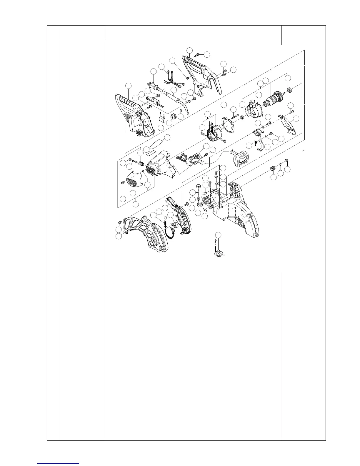
5
Monitor, stator
ass'y, armature
ass'y, pulley (A),
switch, laser
marker
Fig. 62
(1) Remove the two Tapping Screws (W/Flange) D4 x 16 (Black) [344]
to remove the Lever Cover [343].
(2) Remove the two Tapping Screws (W/Flange) D4 x 16 [341] and the
Machine Screw (W/Washers) M4 x 16 [342] to remove the Lever
[339] and the Lever Spring [345].
(3) Remove the three Tapping Screws (W/Flange) D4 x 20 (Black)
[241] and the Machine Screw (W/Washers) M5 x 10 [262] to
remove Switch Handle (R) [269] and Switch Handle (L) [263] from
the Gear Case [275].
(4) Remove the three Tapping Screws (W/Flange) D4 x 20 (Black)
[241] and the Machine Screw (W/Washers) M5 x 25 (Black) [242]
to remove Handle (R) [238] from the Gear Case [275].
(5) Disconnect the three connectors coming from the Monitor [260]
(white: 2 pcs. black: 1 pc.) and remove the two Tapping Screws
(W/Flange) D4 x 30 (Black) [261]. Then the Monitor [260] can be
removed from the Housing Ass'y [251].
Phillips
screwdriver
 Loading...