--- 53 ---
11-3. Reassembly
Reassembly can be accomplished by following the disassembly procedures in reverse. However, special
attention should be given to the following items.
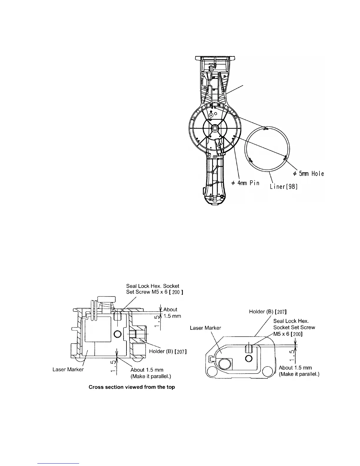
(4) When replacing the Laser Marker [198A], screw the two Seal Lock Hex. Socket Set Screws M5 x 6 [200] into
the Laser Marker [198A]. To adjust the accuracy of the Laser Marker [198A] easily, protrude the tips of the
two Seal Lock Hex. Socket Set Screws M5 x 6 [200] about 1.5 mm from the Laser Marker [198A] using the
2.5-mm hex. bar wrench so that Holder (B) [207] and the Laser Marker [198A] become almost parallel as
shown in Fig. 66-a and Fig. 66-b. Refer to "11-10. Adjustment of Laser Marker Accuracy" for adjustment of the
laser marker accuracy.
Fig. 65
Back of the turn table
Fig. 66-a
(1) Prior to reassembly, measure the insulation
resistance of the armature, stator, switch and
other electrical components and confirm that the
insulation resistance of each part is more than
5 M Ω.
(2) When replacing the Spring [152], apply 3 grams
of Hitachi Motor Grease to the inner
circumference of the new spring prior to
assembly.
(3) When replacing or reassembling the Liner [98],
ensure it is positioned and assembled as
illustrated in Fig. 65. In addition, coat 10 grams
of Hitachi Motor Grease on the liner sliding
portion of the Turn Table [26].
Fig. 66-b
Cross section viewed from the front
[198A]
[198A]
 Loading...