7 ELECTRICAL WIRING
! DANGER
• The electrical wiring work must be performed by authorized
installers.Ifnot,itmaycauseanelectricshockorare.
• Perform the electrical work according to each regulation of
region and “Installation and Operation Manual ”, and the
dedicatedelectricalcircuitmustbeused.Ifnotperformingthe
electricalwiringworkcompletelyoracapacityshortageofthe
powercircuit,itwillcauseanelectricshockorare.
• InstallanELB(EarthLeakageBreaker:2/40/30n/A/mA)and
CB(CircuitBreaker:5A)inthepowersource.Ifnotused,itwill
causeanelectricshockorare.
• Turn OFF the main power switch of the indoor unit and the
outdoor unit before an electrical wiring work or a periodical
checkisperformed.Ifnot,itwillcauseanelectricshockorare.
• Protect the wires, drain pipe, electrical parts, etc. from rats
or other small animals. If not protected, rats may gnaw at
unprotectedpartsandattheworst,arewilloccur.
• Selectthewiringsize,ELB(EarthLeakageBreaker)andisolating
switchaccordingtoeachregulationofregionand“Installation
&OperationManual”,andthededicatedelectricalcircuitmust
beused.
• Tightenscrewsaccordingtothefollowingtorque.
M3.5: 1.2 N-m
M4: 1.0 to 1.3 N-m
• Connectearthwiresfortheoutdoor/indoorunittopreventan
electricalshockoranunexpectedaccident.Theearthresistance
mustbelessthan1megohm.Theearthworkmustbeperformed
byauthorizedinstallers.
• Pay attention not to bite electrical wirings when attaching the
servicecover.Itmaycauseanelectricalshockorre.
! CAUTION
• Make sure that the eld-selected electrical components (main
power switches, circuit breakers, wires, conduit connectors and wire
terminals) have been properly selected according to the electrical
data given in “Technical Catalog”. Make sure that the components
comply with National Electrical Code (NEC).
• Check to ensure that the electrical resistance is more than 1 megohm,
by measuring the resistance between ground and the terminal of the
electrical parts. If not, do not operate the system until the electrical
leakage is found and repaired.
• Do not connect the main power source cables to the control line
(Terminals A, B, 1 and 2 of TB2). If connected, the printed circuit
board (PCB) will be broken.
Power source cable size Transmitting cable size
EN 60335-1 *1 EN 60335-1 *1
0.75mm
2
0.75mm
2
? NOTE
• Follow local codes and regulations when selecting eld wires.
• The wire sizes marked with *1 in the above table are selected at the
maximum current of the unit according to the European Standard,
EN 60335-1. Use the wires which are not lighter than the ordinary
tough rubber sheathed exible cord (code designation 60245 IEC 57)
or ordinary polychloroprene sheathed exible cord (code designation
60245 IEC 57).
• Use the shielded twisted pair cable for control between the outdoor
unit and the indoor unit, the control cable between indoor units and
the remote control switch cable.
Harmonics
In relation to IEC 61000-3-2, the situation of harmonics for each
model is as follows:
Situation of the models in relation to IEC
61000- 3-2
Model
Equipment complying with IEC 61000-3-2 RPI-(1.5-2.0)FSRE
Installation restrictions may be applied by
supply authorities in relation to harmonics
RPI-(2.5-6.0)FSRE
Details of electrical wiring connection
1 Use shielded twisted pair cable for the control cable between
the outdoor unit and the indoor unit, between indoor units.
They are connected to the terminals 1 and 2 of the terminal
boards. The total cable length should be less than 1000m.
2 Use shielded twisted pair cable for the remote control switch
cable. The total cable length should be less than 500m. If the
total length of the cable is less than 30m, other cables can
be used (0.3 to 0.75mm2 ) if comply with local regulations.
The remote control shielded twisted pair cable is connected
to the terminals A and B of each indoor unit terminal board.
3 Check to ensure that the communication cable between
outdoor unit and indoor units (H-Link), comply with Local
regulations and it is not aected by any electromagnetic
noise. It must be a shielded twisted pair cable (≥0.75mm2)
with a total H-Link length <1000m.
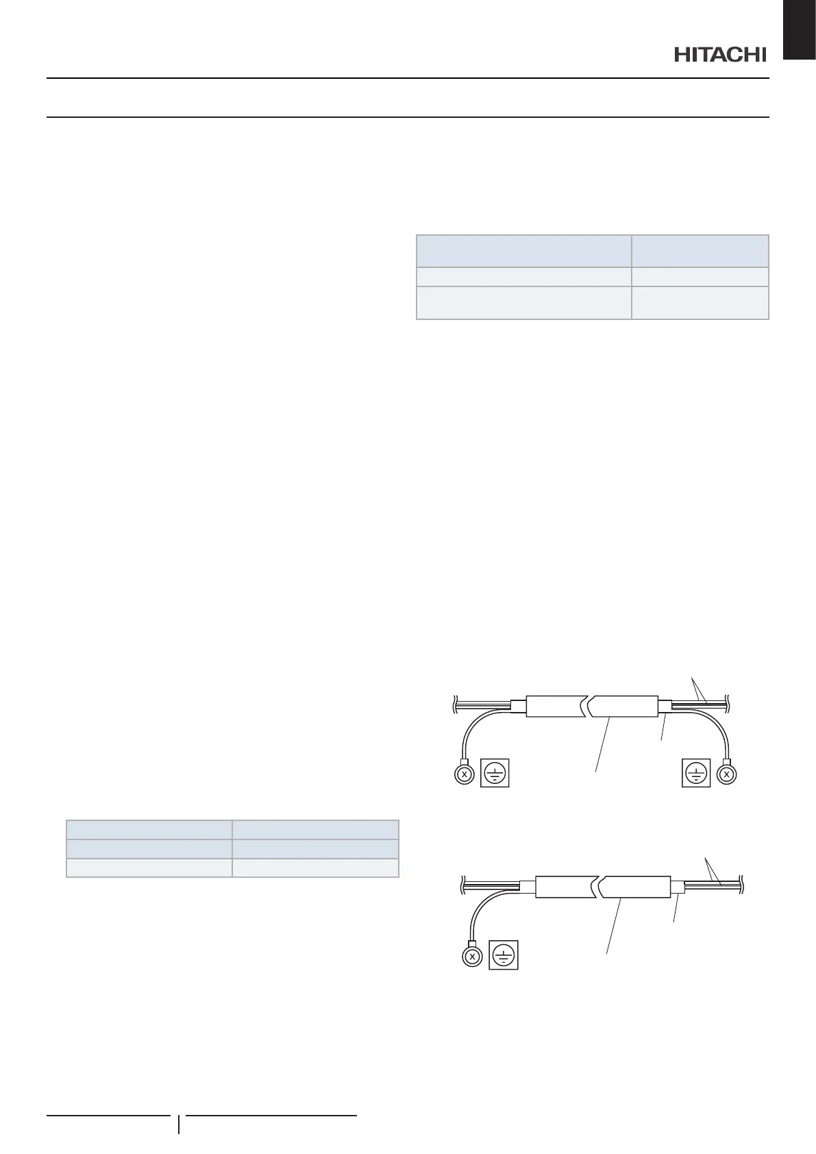
4 Control cable: connect the both ends of shielded twisted pair
cable to the earth as shown.
Earth
Earth
Shielded twisted pair cable
Wires
Shield
5 Remote control switch cable: Connect the one end of
shielded twisted pair cable to the earth as shown.
Earth
Shielded twisted pair cable
Wires
Shield
ELECTRICAL WIRING
PMML0528 rev.1 - 02/2021
19
EN
 Loading...

