3 Tighten the screws on terminals L1 and N.
4 Check that the cables are correctly secured.
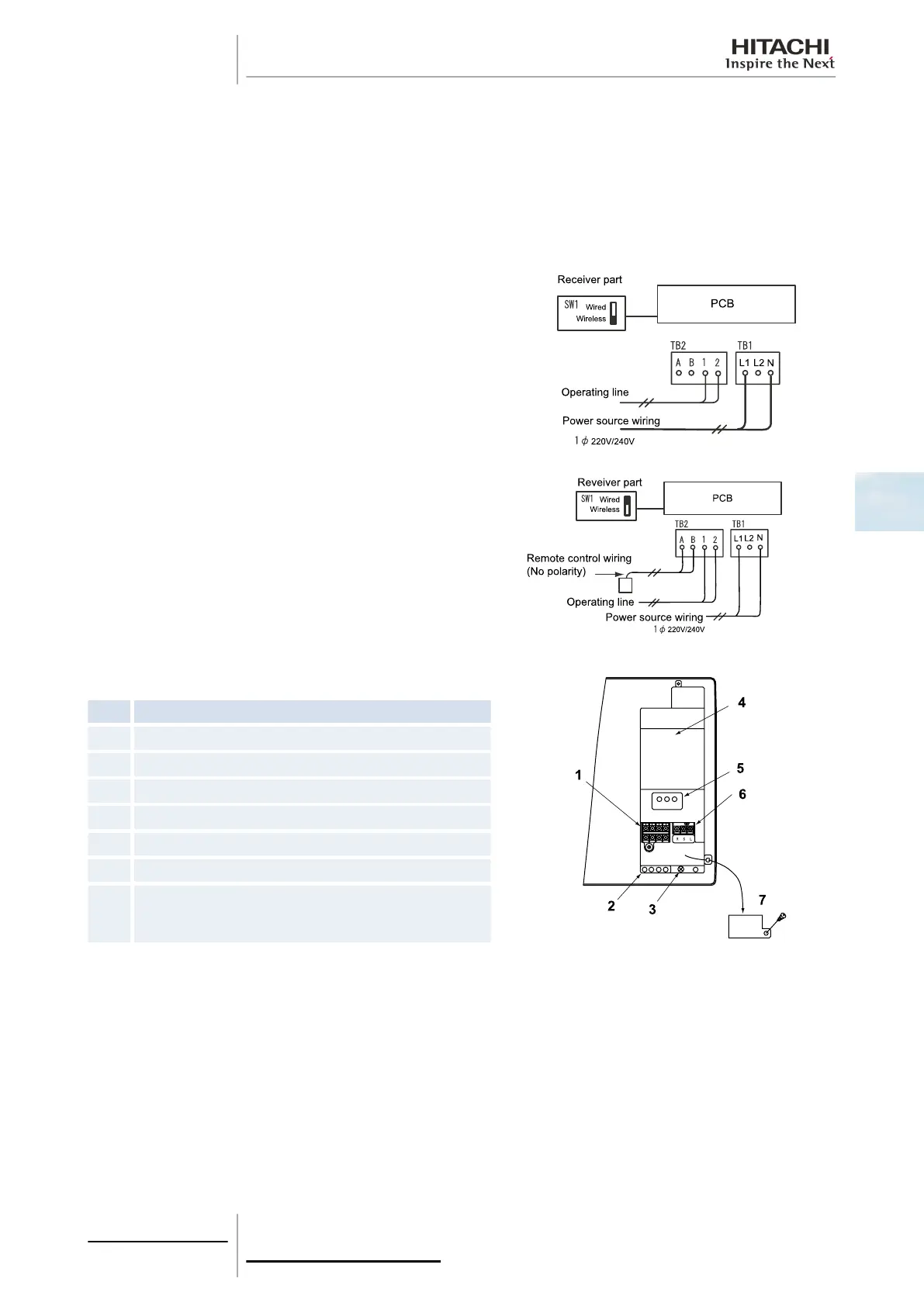
Follow the steps below to connect the communication cables between the outdoor and indoor unit to the terminal strip
(TB2):
1 Where necessary, loosen the screws on terminals 1 and 2 on the terminal strip (TB2).
2 Connect the communication cables to terminals 1 and 2.
3 Tighten the screw on terminals 1 and 2.
4 Check that the cables are correctly secured.
Follow the steps below to connect the earth wire to the earth
connection in the electrical box:
1 Where necessary, loosen the screw on the earthing connection
in the electrical box.
2 Connect the shielded part of the power supply earth wire and
the signal wiring earth wire to the earth connection.
3 Tighten the screw on the earthing connection in the electrical
box.
4 Check that the shielded part of the earthing cables are correctly
secured.
Connection with remote control:
RPK-(1.0/1.5)FSN(H)2M terminal board connections
Nº
Part
1 Terminal strip (TB2)
2 Cable tie
3 Earthing screw
4 Electrical box cover
5 Printed circuit board (PCB) of the receiver
6 Terminal strip (TB1)
7
Screw on right side of the electrical box (to open and
connect the power wiring and the remote control wiring
between the indoor and outdoor unit).
4 Electrical wiring
129
SMGB0063 rev. 1 - 10/2010
4
 Loading...


