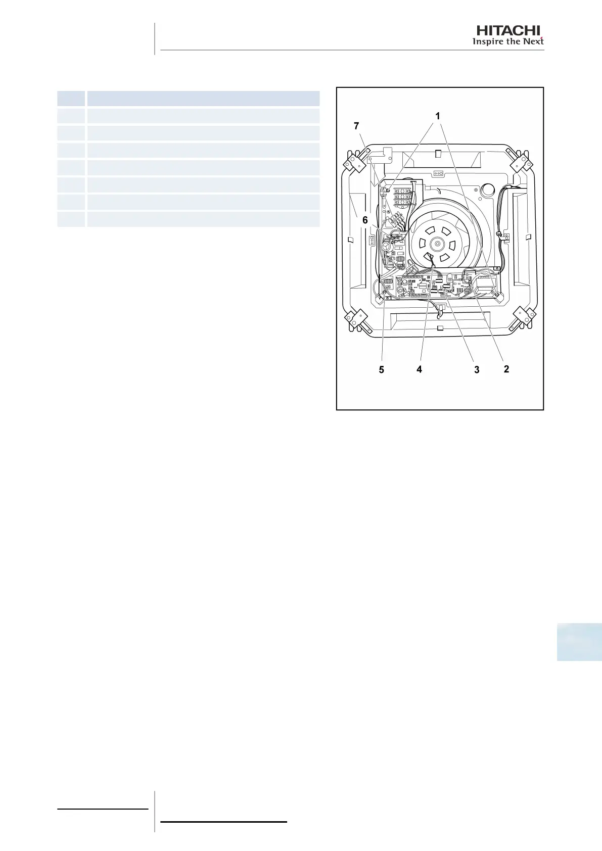
10.2.5 Removal of the electrical box
Nº Part
1 Electrical box set screw
2 Drainage pump connector (PCN6)
3 Automatic louver connector (CN17)
4 Outlet thermistor (THM2)
5 Automatic louver electrical box set screw (THM2)
6 Fan motor connector (CN203)
7 Fan motor connector (CN201)
Remove the air inlet grille as indicated in chapters Removal of the
air filter, see on page 277 and Removal of the air inlet grille, see
on page 277.
Remove the electrical box as follows:
1 Remove the electrical box cover.
2 Disconnect the thermistors (THM2), the drainage motor
connector (PCN6), the float switch connector (CN14), the
automatic louver connector (CN17) and the fan motor
connector (PCN203, CN201) from the PCB.
3 Remove the three set screws from the electrical box and
remove carefully.
10 Servicing
279
SMGB0063 rev. 1 - 10/2010
10
 Loading...


