Remove the tie securing the outlet air thermistor. Cut the aluminium
tape not securing the right-hand side of the electrical box.
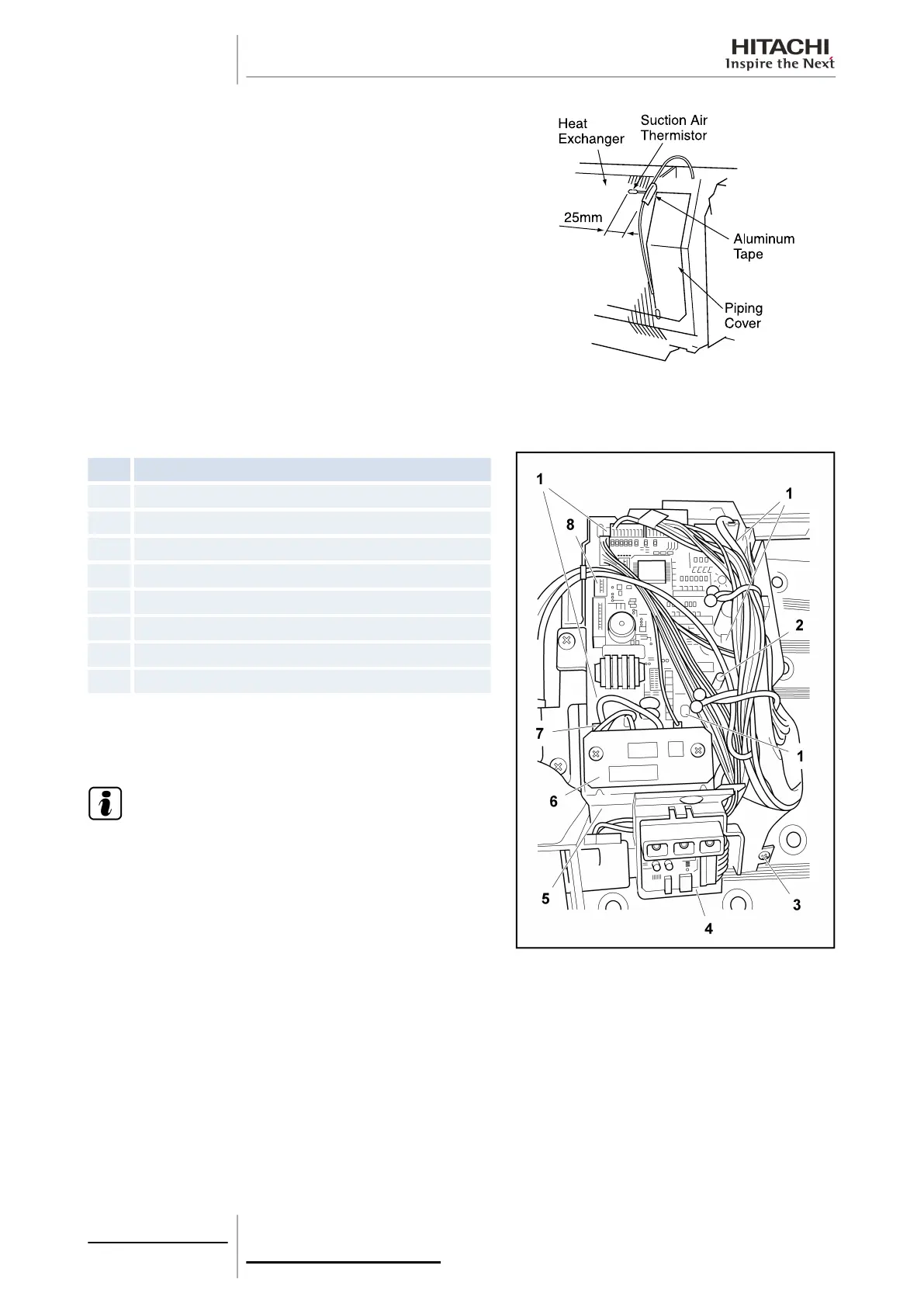
10.8.8 Removal of the printed circuit board (PCB)
RPK-(1.0/1.5)FSN(H)2M
Nº
Part
1 Spacer
2 Set screw for the earthing wire
3 Set screw for the receiver
4 Receiver PCB
5 Receiver cover fixture
6 Operating PCB
7 Connector for the operating PCB
8 Connector for the receiver part
Remove the electrical box as indicated in section Remove the
electrical box panel, see on page 329.
Remove the connector from the control PCB.
N O T E
The expansion valve connector cannot be removed.
10 Servicing
332
SMGB0063 rev. 1 - 10/2010
 Loading...


