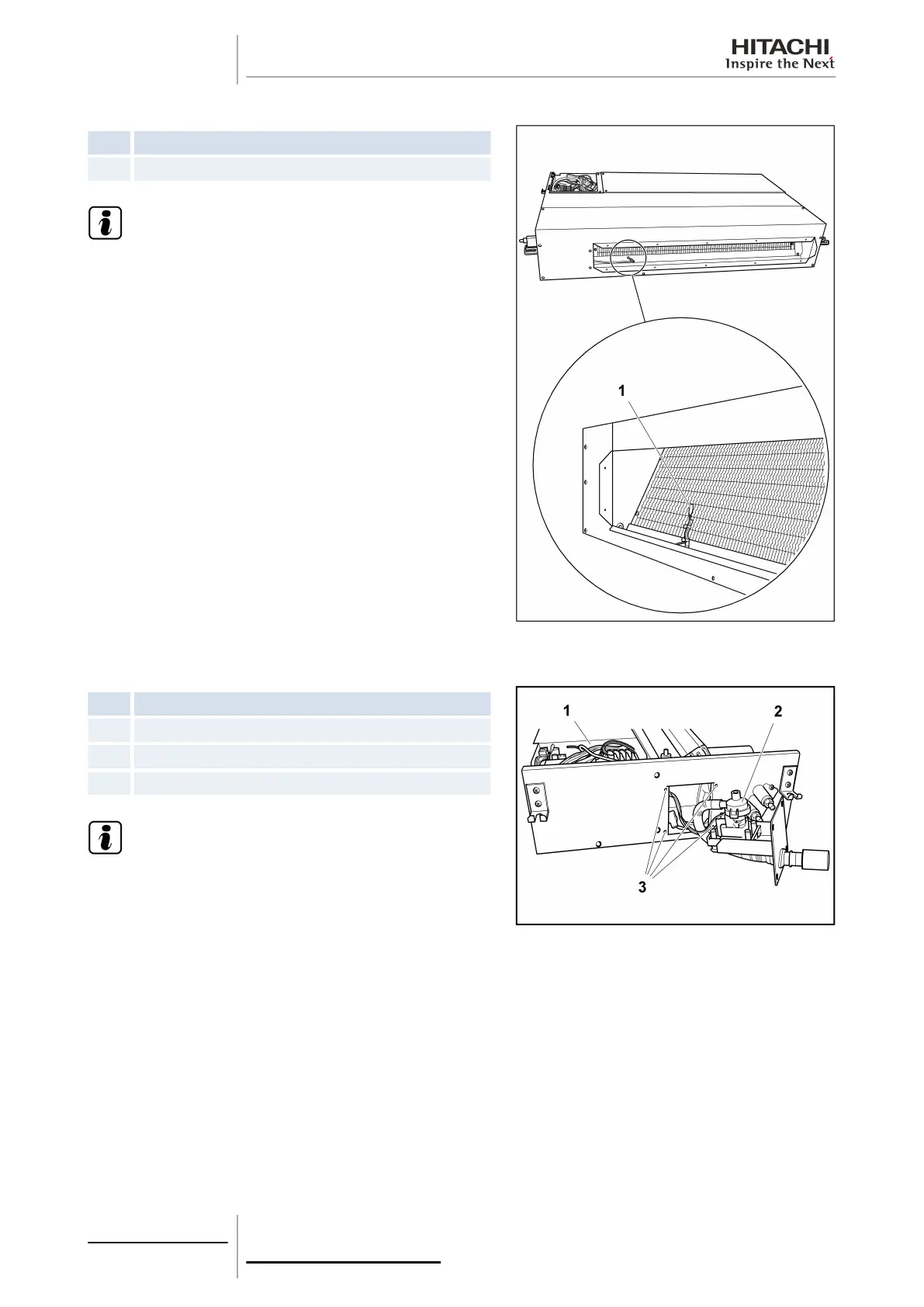
Outlet air thermistor
Nº Part
1 Air outlet thermistor
N O T E
To disconnect and remove the appropriate thermistor,
previously see the chapter corresponding to the wiring
diagrams in this Manual.
10.4.3 Removal of the thermistors from the liquid and gas pipes
Nº
Part
1 Electrical box
2 Drain pump
3 Screws
N O T E
• To disconnect and remove the appropriate thermistor,
previously see the chapter corresponding to the wiring
diagrams in this Manual.
• Cover the thermistors with cork tape or pipe insulation,
depending on the location. Both materials are factory-
supplied. Replace them if damaged during maintenance work.
Remove the electrical box cover.
Remove the service cover.
The liquid and gas pipe thermistors are secured to the copper piping by a special clamp.
• Liquid pipe thermistor: covered with cork tape.
• Gas pipe thermistor: covered with pipe insulation.
10 Servicing
298
SMGB0063 rev. 1 - 10/2010