10.5 RPI-(8.0-10.0)FSN2E - Ducted indoor unit
10.5.1 Removal of the electrical box cover
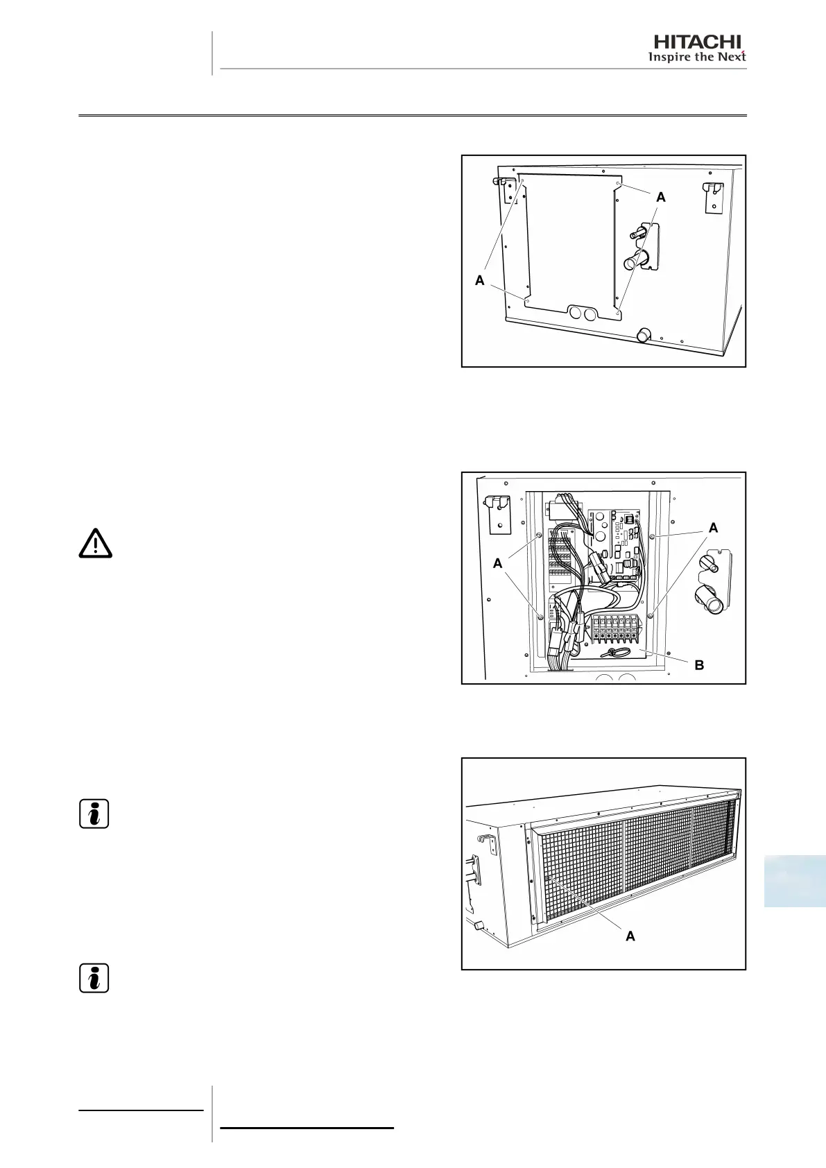
Remove the set screws -A- from the electrical box cover to access
the electrical components.
10.5.2 Removal of electrical components
Remove the electrical box cover Removal of the electrical box cover, see on page 303.
Separate the connections of all electrical components.
Remove the set screws -A- and separate the full electrical
component support -B-.
C A U T I O N
Handle the support carefully to avoid damaging the electrical
components.
10.5.3 Removal of the inlet and outlet air thermistors
Inlet air thermistor
Remove the air filter Removal of the air filter, see on page 308.
N O T E
The inlet air thermistor -A- is located on the left-hand side of
the air inlet to the unit.
Remove the electrical box cover Removal of the electrical box
cover, see on page 303.
Disconnect and remove the thermistor.
N O T E
To disconnect and remove the appropriate thermistor, previously see the chapter corresponding to the wiring
diagrams in this Manual.
10 Servicing
303
SMGB0063 rev. 1 - 10/2010
10
 Loading...


