N O T E
• The symbol “■” indicates the position of the DIP switches. The figures show the setting before transmission
or after selection.
• If the “■” mark is not displayed, this indicates that the position of the pin is not affected.
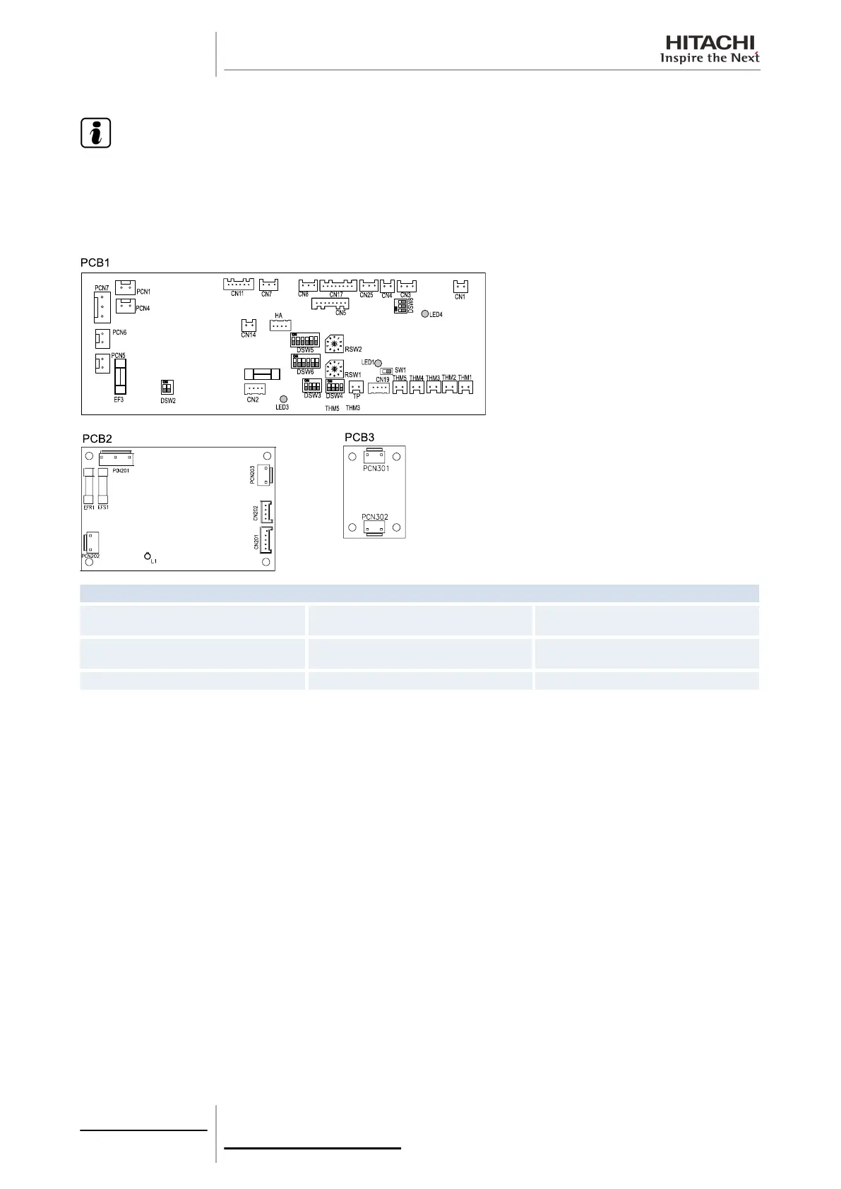
The indoor unit PCB operates with five types of DIP switches and two rotary switches. The position is as follows:
LED indicator
LED1 Red
This LED indicates the transmission status
between the indoor unit and the remote control.
LED3 Yellow
This LED indicates the transmission status
between the indoor unit and the outdoor unit.
LED4 Red PCB power supply
5 Control system
162
SMGB0063 rev. 1 - 10/2010
 Loading...


