RPK-(1.0/1.5)FSN(H)2M
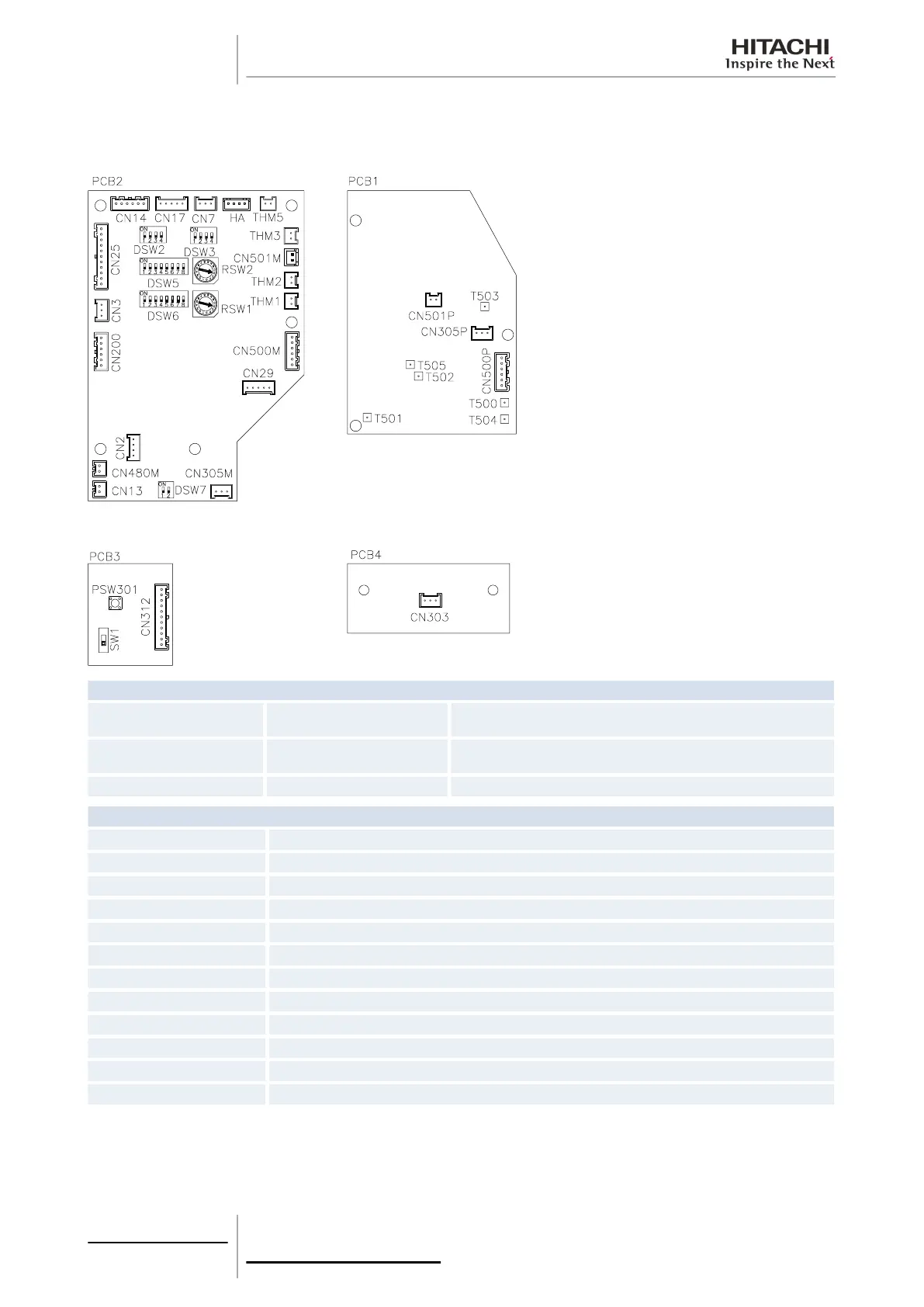
The indoor unit PCB operates with four types of DIP switches, a slide switch, a rotary switch and a button switch. The
position is as follows:
LED indicator
LED1 Red
This LED indicates the transmission status between the indoor unit and the
remote control.
LED3 Yellow
This LED indicates the transmission status between the indoor unit and the
outdoor unit.
LED4 Red PCB power supply
Connector indication
THM1 Air inlet
THM2 Air outlet
THM3 Freeze protection
THM5 Gas pipe
CN2 Outdoor unit H-LINK control circuit
CN3 Optional input functions
CN7 Optional output functions
CN13 SW remote control
CN14 Expansion valve control
CN17 Swing louver motor
CN25 Connection of the PCB3 wireless receiver part
CN29 Fan motor
5 Control system
170
SMGB0063 rev. 1 - 10/2010
 Loading...


