Model A B C D E F G
RPF-1.5FSN2E 1170 879 217 857 228 140 630
RPFI-1.5FSN2E 988 879 66 857 77 138 620
RPF-2.0FSN2E
1420 1129 11 1107 228 140 630
RPF-2.5FSN2E
RPFI-2.0FSN2E
1234 1129 11 1107 53 139 620
RPFI-2.5FSN2E
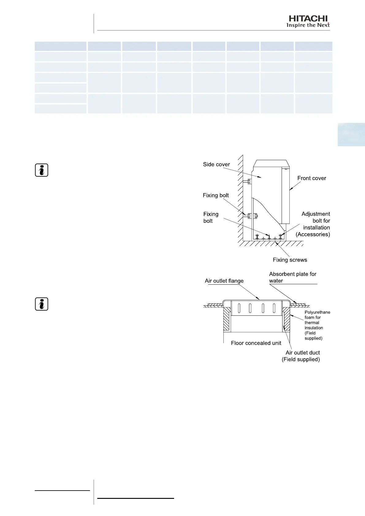
Adjust the horizontal level of the unit by loosening or tightening the unit installation bolts.
Check that the condensate discharge system in the unit works correctly. To do so, check the level of the drain pan using a
spirit level. The side of the unit on which the drain hose is located must be around 3 mm lower than the opposite side.
Secure the base plate and the rear plate of the unit using field-supplied bolts and screws.
N O T E
• RPFI units: remove the electrical wiring box when fitting
the installation bolts.
• RPF units: carry out the above operation after removing
the front and side covers of the unit.
RPFI unit: install the optional air outlet grille as indicated in the
figure.
N O T E
• Condensation may be accumulated if the unit is installed
in a very damp place. Install a porous, water-absorbent
plastic plate to absorb and retain water around the grille.
• The optional air outlet grille of the RPFI unit cannot be used
in very damp places, such as a kitchen or bathroom, as
condensation may settle on its surface.
RPFI units: Install an additional access cover attached with screws so as not to touch the fan duct directly.
2 Unit installation
59
SMGB0063 rev. 1 - 10/2010
2
 Loading...


