22
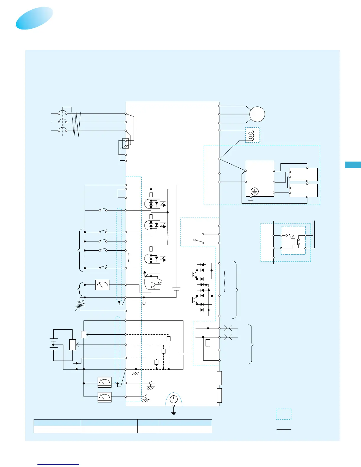
CONNECTING DIAGRAM
■Source type logic
Terminal Name
Common terminal
FW, 1, 2, 3, 4, 5, 6, 7, 8 FM, TH H, O, O2, OI, AM, AMI
L
Frequency
setting device
500
-
2kΩ
DC0
-
10V
(12bit)
DC0
-
10V(8bit)
(G)
DC
-
10
-
+10V
(12bit)
DC4
-
20mA(12bit)
DC4
-
20mA(8bit)
DC0
-
10V
IM
SJ300
R(L1)
S(L2)
T(L3)
R
P24
PLC
CM1
FW
8
7
6
1
FM
CM1
O2
OI
L
AM
AMI
10kΩ
10kΩ
100Ω
TH
H
O
T(J51)
SN
RP
SN
SP
(T3)W
(T2)V
(T1)U
AL2
AL1
AL0
DC24V
DC10V
-
+
15
11
CM2
R0
T0
200V
-
240V±10%
50/60Hz±5%
In case of 400V class, place a transformer for operating circuit to receive 200V.
NN
P
RB
R1
R2
RB
P
(+1)PD
(*2)Remove connection with J51
when RoTo power is supplied
externally
(*2)
AL1
AL2
AL1
AL2
RB
P
RB
P
P
RB
P
RB
N
(
+
)
(
-
)
Control power source
Short-circuit
bar
Forward command
Intelligent input
terminals (8 terminals)
FM monitor output
(PWM)
Thermistor
DC link choke
Dynamic braking unit (BRD)
For 15kW(20HP) and over
Intelligent relay
output contacts
(Inverter)
Braking resistor
(
RB
)
(To operating circuit)
Intelligent output terminals
RS-485
Serial communication port
Expansion card 1
Expansion card 2
AM monitor output
(Analog output)
AM monitor output
(Analog output)
For up to 11kW(15HP)
Option
Customer wiring
(Outside the inverter)
P24 CM1

 Loading...


