38
The internal themal contact capacity is 250V
AC, 2A max. It is on under nomal condition
(NC contact).
Prevents abnormal heat resulting from the
incorrect use by internal temperature fuse.
(recovery not possible).
When the temperature relay is activated,
reduce regenerative energy by stopping the
inverter or by increasing deceleration time.
Note 1:
2:
3:
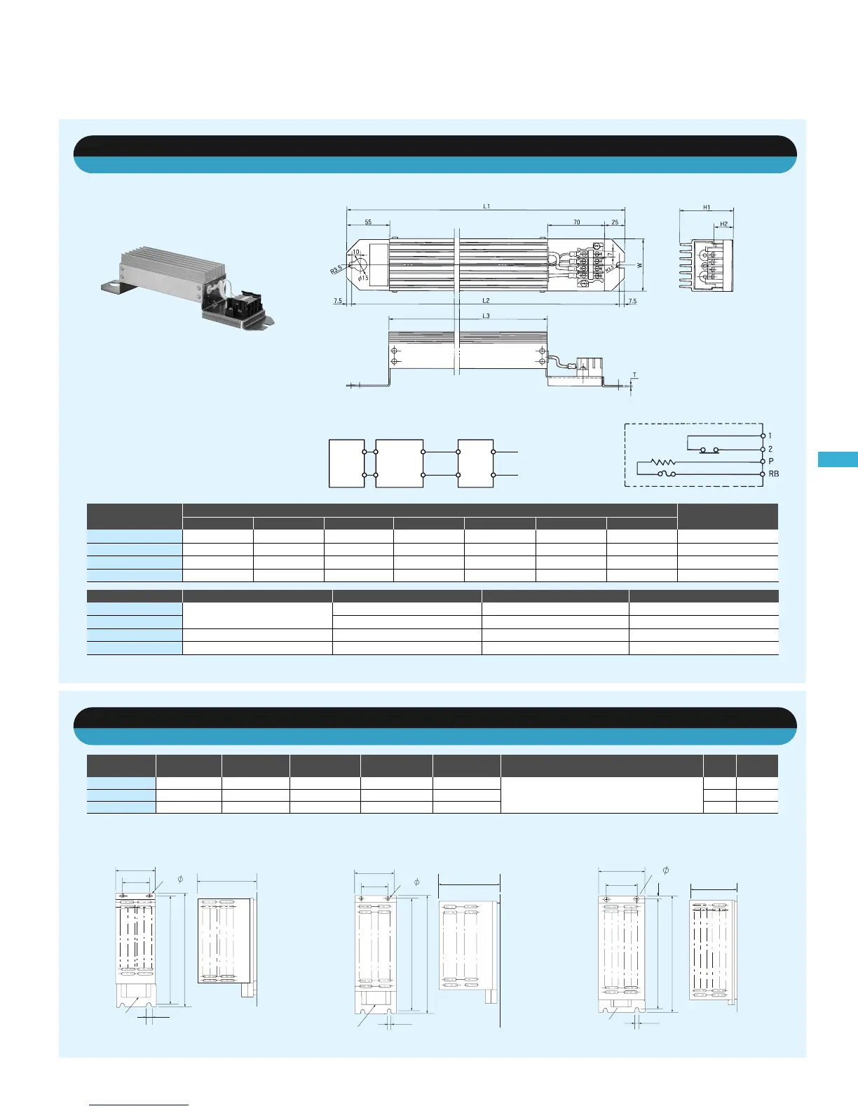
●Dimensional Drawings
●Circuit Diagram
●Connecting Diagram
Braking Resistor
(
Standard type
)
SRB-□□□
Braking Resistor
(
Medium capacity type
)
RB1, RB2, RB3
Alarm contact
(NC contact)
ON under normal
condition
P
RB
PP
RB
1
2
P
NN
Dynamic
braking unit
Braking resistor
Inverter
[Figure 1]
[Figure 2]
[Figure 3]
●Dimensional Drawings
[Unit: mm]
Model name
RB1
RB2
RB3
50
35
17
400
600
1200
2600
3800
7700
10
10
10
2.5
3.6
6.5
1
2
3
Resistance value
(
Ω
)
Rated capacity
(
W
)
Instantaneous capacity
(
W
)
Allowable braking cycle
(
%
)
10
10
10
Allowable continuous
ON period
(
sec.
)
Thermal relay (NC contact) inside the resistor is
activated at abnormal high temperature.
Contact rating AC240V, 3A
(
R load
)
, 0.2A
(
L load
)
DC36V, 2A
(
R load
)
Weight
(
kg
)
Overheat protection Figure
[Unit: mm]
Modelname
SRB 200-1
SRB 200-2
SRB 300-1
SRB 400-1
L3L2
310
310
470
435
295
295
455
422
160
160
320
300
67
67
67
94
12
12
12
15
64
64
64
76
1.6
1.6
1.6
2.0
0.97
0.97
1.68
2.85
H1
Dimension
(
mm
)
H2 W
Weight
(
kg
)
L1 T
Modelname
SRB 200-1
SRB 200-2
SRB 300-1
SRB 400-1
200W
300W
400W
180Ω
100Ω
50Ω
35Ω
10%
7.5%
7.5%
7.5%
30sec.
30sec.
30sec.
20sec.
Resistancevalue Allowable continuous ON periodCapacity Allowablebrakingcycle
Terminal
block
Terminal
block
Terminal
block
150
110
170
7
10
390
410
2- 7
150
100
70
390
410
2 - 5
5
100
150
70
5
280
300
2 - 5
For rated capacity, one cycle is within 100 sec.
Please connect the same two braking resistors with the series when using for class of 400V.
Note 1:
2:
Please connect the same two braking resistors with the series when using for class of 400V.
Note 1:

 Loading...


