16
Assembly
Assembly instructions
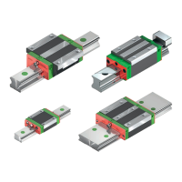
Linear Guideways
GW-04-0-EN-1910-MA
B. Tensioning the profile rail with the machine bed
X Tighten the terminal block’s allen set screws in order to press the profile rail firmly on to the machine’s stop edge.
X Working in three steps, tighten the fixing screws on the profile rail using a torque spanner to the specified tightening
torque.
A list of optimum screw tightening torques can be found in Section 12.2 on page 57.
Maintain the permissible tolerances for the mounting surfaces and mounting deviations of the relevant series, in
accordance with Sections 3.3, 3.4 and 3.5.
The profile rail has now been assembled.
The profile rails can be tensioned using a terminal block or vices.
Tensioning the profile rail using a terminal block:
Tensioning the profile rail using vices:
X Use the vices to press the profile rail against the machine bed’s stop edge.
X Tighten the profile rail’s fixing screws.
X Repeat this process for all fixing points.
X Working in three steps, tighten all fixing screws on the profile rail using a torque spanner to the specified tightening
torque.
A. Aligning the profile rail.
X Place the reference side of the profile (see Section 5.2.1) rail against the machine bed’s stop edge.
X Loosely attach the fixing screws.
5.2.4 Assembling the profile rail at a stop edge
Fig. 5.6 Aligning of the profile rail with the stop edge
Fig. 5.7 Tensioning using a terminal block
 Loading...