Assembly
31
Assembly instructions
Linear Guideways
GW-04-0-EN-1910-MA
5.4.2.1 Specificity in the assembly of QH, QE and QW blocks
Table 5.3 Maximum lengths for fixing screws – QH, QE and QW blocks
Model Max. screw length M × L [mm] Model Max. screw length M × L [mm]
QHH20 M5 × 6 QEH25 M6 × 9
QHH25 M6 × 8 QEH30 M8 × 10
QHH30 M8 × 10 QWH27 M6 × 6
QHH35 M8 × 12 QWH35 M8 × 8
QEH20 M5 × 7
M × L
Fig. 5.41 Depiction of bore hole and recirculation channel
Failure to comply with the maximum screw length can cause damage to the block.
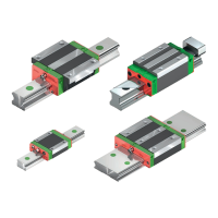
The block mounting holes for the HIWIN rail guideways in the QH, QE and QW series are linked to the ball return channels
(see Fig. 5.41). Using screws that are too long can damage the rolling elements.
X Do not exceed the maximum screw lengths specified in Table 5.3!
ATTENTION!
The linear guideway’s load-bearing capacity is often restricted – not by its load-bearing strength, but by the
screw connection. We therefore recommend checking the screw connection’s maximum permissible load-
bearing capacity in accordance with VDI 2230.
5.4.2.2 Specific features to bear in mind when assembling an adjacent structure on RG, QR and CG blocks
Each block in the RG, QR and CG series is provided with two additional central threaded holes. These are sealed with green
seal stoppers on delivery.
In order to achieve high rigidity for the linear guideway even in cases of high loads, we generally recommend using all avail-
able threaded holes to fix the adjacent structure in place.
In blocks from the RGW and QRW series, you also have the option of securing your adjacent structure from
below. Before the block is assembled, it must be secured to the adjacent structure.
 Loading...