EasyManuals Logo

Hobart Handler 135 User Manual

Hobart Handler 135
48 pages
To Next Page IconTo Next Page
To Previous Page IconTo Previous Page
Page #15 background imageLoading...
Page #15 background image
OM-944 Page 11
2-3. Volt-Ampere Curves
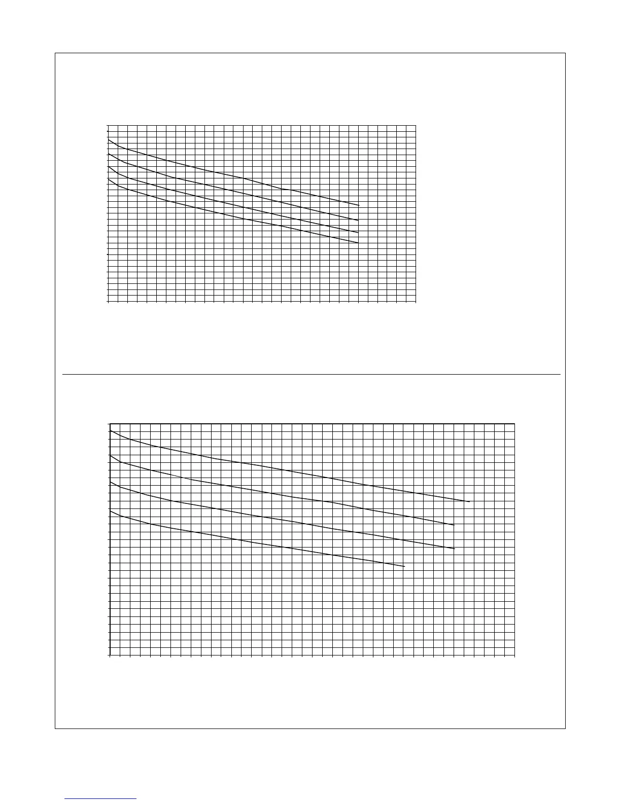
The volt-ampere curves show the
minimum and maximum voltage
and amperage output capabilities of
the welding power source. Curves
of other settings fall between the
curves shown.
ssb1.1 10/91 196 608 / 196 609
A. 115 VAC Model
B. 230 VAC Model
0.0
5.0
10.0
15.0
20.0
25.0
30.0
0 10 20 30 40 50 60 70 80 90 100 110 120 130 140 150 160
LOAD AMPS
OUTPUT VOLTS
Range 4
Range 3
Range 2
Range 1
0.0
5.0
10.0
15.0
20.0
25.0
30.0
0 10 20 30 40 50 60 70 80 90 100 110 120 130 140 150 160 170 180 190 200
LOAD AMPS
OUTPUT VOLTS
Range 4
Range 3
Range 2
Range 1

Table of Contents

Questions and Answers:

Question and Answer IconNeed help?

Do you have a question about the Hobart Handler 135 and is the answer not in the manual?

Hobart Handler 135 Specifications

General IconGeneral
Amperage Output25-135A
Wire Feed Speed40-700 IPM
Input Current20A
Output Current Range25 - 135 A
Welding ProcessesMIG (GMAW)
Maximum Material Thickness1/4 inch
Input Frequency60 Hz
Wire Size Range0.023-0.035 inch
Input PhaseSingle Phase

Related product manuals