EasyManuals Logo

Hobart Handler 135 User Manual

Hobart Handler 135
48 pages
To Next Page IconTo Next Page
To Previous Page IconTo Previous Page
Page #29 background imageLoading...
Page #29 background image
OM-944 Page 25
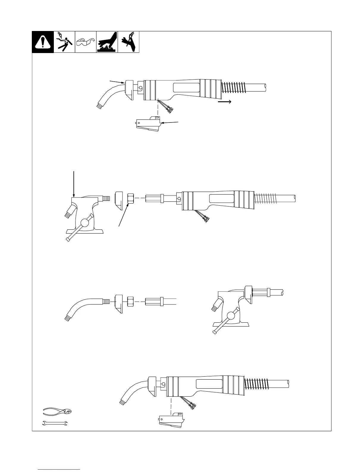
5-7. Replacing Switch And/Or Head Tube
Ref. ST-800 795-C
Tools Needed:
19 mm
Remove handle
locking nut.
Slide handle.
Secure head
tube in vice.
Loosen jam nut.
Remove from vice
and turn head tube
out by hand.
Hand-tighten head tube into cable connector.
Place head tube in vice and tighten until
nuts are tight.
Remove from vice. Reposition handle and install
switch housing. Secure with handle locking nut.
Y Turn Off welding power source
/wire feeder and disconnect gun.
Remove switch housing. Install new switch and
connect leads (polarity is not important). Reas-
semble in reverse order. If replacing head tube,
continue to end of figure.
1
3
2
4
5
8
6
7

Table of Contents

Questions and Answers:

Question and Answer IconNeed help?

Do you have a question about the Hobart Handler 135 and is the answer not in the manual?

Hobart Handler 135 Specifications

General IconGeneral
Amperage Output25-135A
Wire Feed Speed40-700 IPM
Input Current20A
Output Current Range25 - 135 A
Welding ProcessesMIG (GMAW)
Maximum Material Thickness1/4 inch
Input Frequency60 Hz
Wire Size Range0.023-0.035 inch
Input PhaseSingle Phase

Related product manuals