EasyManuals Logo

Hobart Handler 135 User Manual

Hobart Handler 135
48 pages
To Next Page IconTo Next Page
To Previous Page IconTo Previous Page
Page #16 background imageLoading...
Page #16 background image
OM-944 Page 12
SECTION 3 INSTALLATION
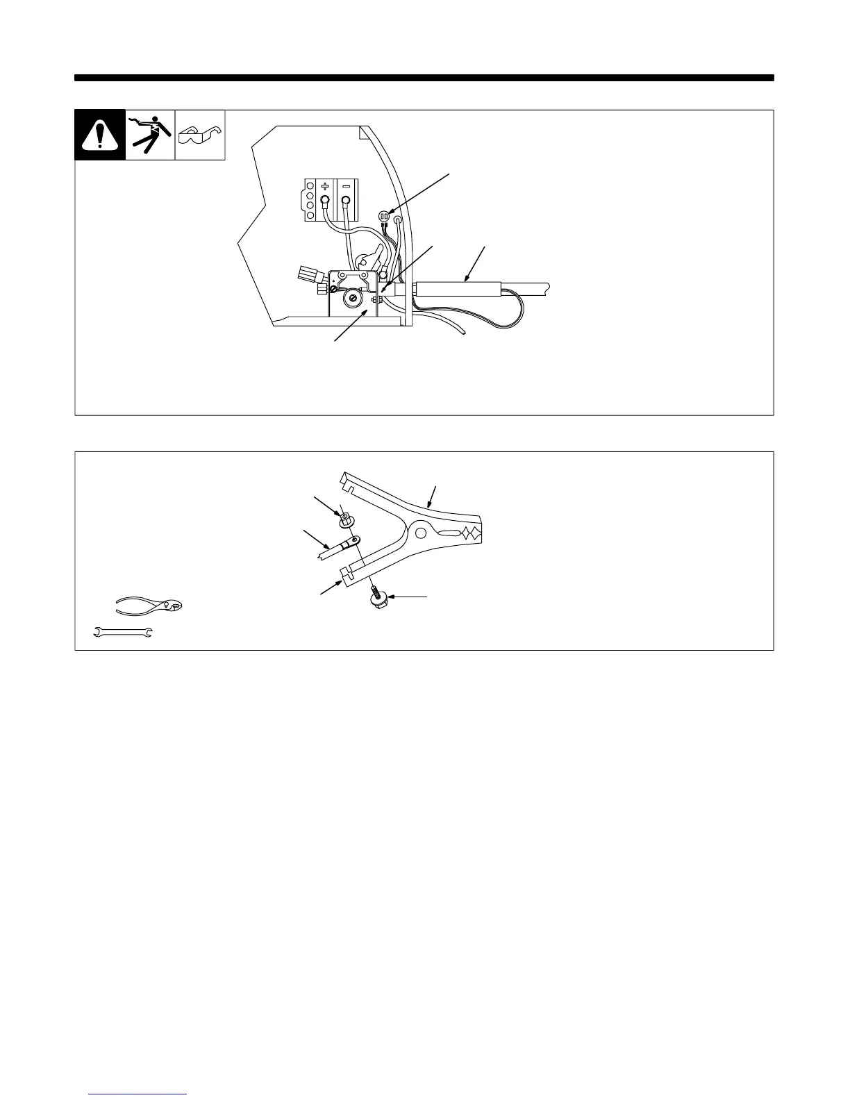
3-1. Installing Welding Gun
Ref. 802 440
1 Drive Assembly
2 Gun Securing Thumbscrew
3 Gun End
Loosen thumbscrew. Insert gun
end through opening until it bottoms
against drive assembly. Tighten
thumbscrew.
4 Gun Trigger Leads
Insert leads, one at a time, through
gun opening on front panel.
Connect female friction terminals to
matching male terminals in unit.
Polarity is not important.
Close door.
4
1
2
3
3-2. Installing Work Clamp
1 Nut
2 Work Cable From Unit
3 Work Clamp
4 Screw
5 Work Clamp Tabs
Bend tabs around work cable.
802 456
1
2
3
4
5
Tools Needed:
3/8, 7/16 in

Table of Contents

Questions and Answers:

Question and Answer IconNeed help?

Do you have a question about the Hobart Handler 135 and is the answer not in the manual?

Hobart Handler 135 Specifications

General IconGeneral
Amperage Output25-135A
Wire Feed Speed40-700 IPM
Input Current20A
Output Current Range25 - 135 A
Welding ProcessesMIG (GMAW)
Maximum Material Thickness1/4 inch
Input Frequency60 Hz
Wire Size Range0.023-0.035 inch
Input PhaseSingle Phase

Related product manuals