EasyManuals Logo

Hobart Handler 135 User Manual

Hobart Handler 135
48 pages
To Next Page IconTo Next Page
To Previous Page IconTo Previous Page
Page #20 background imageLoading...
Page #20 background image
OM-944 Page 16
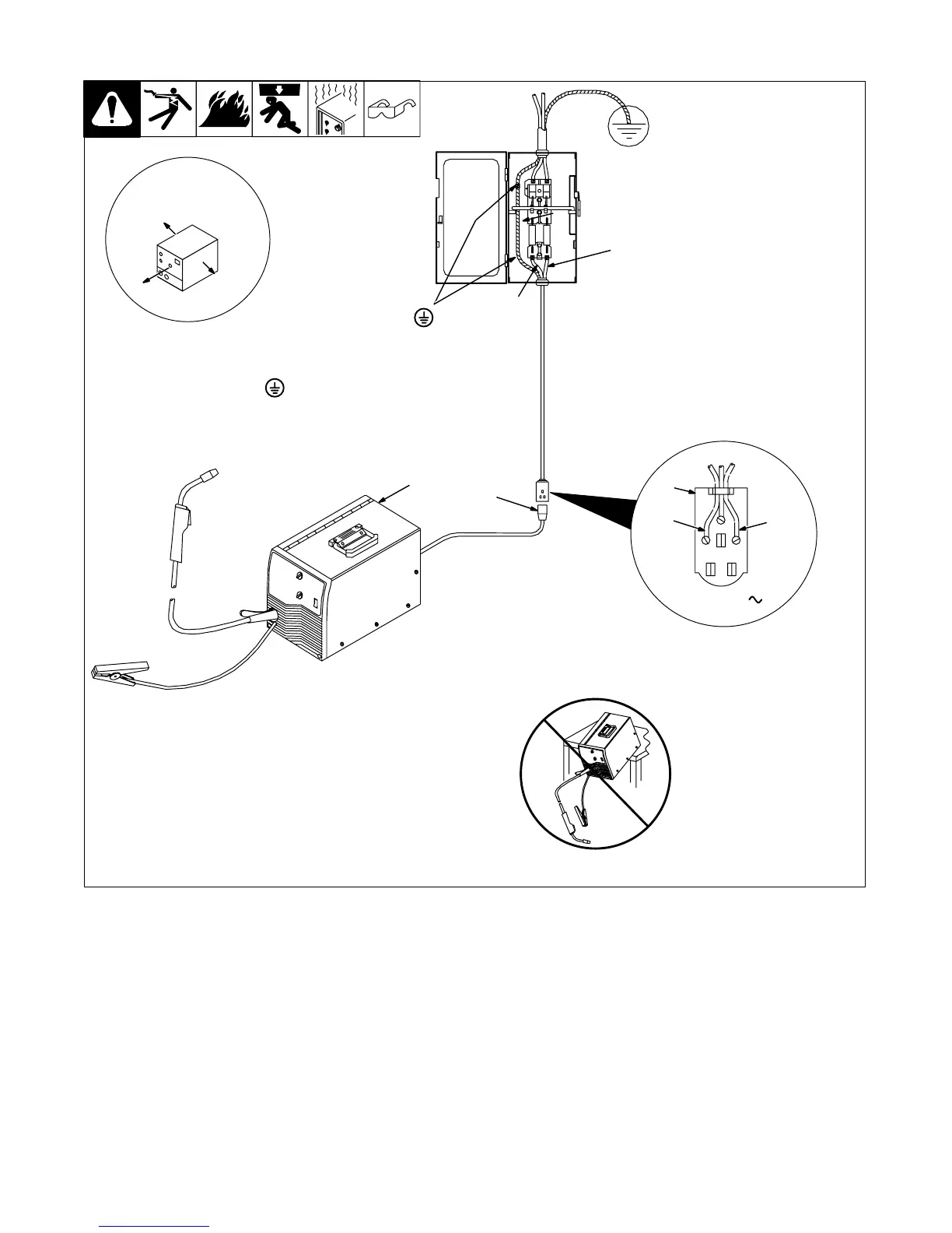
3-7. Selecting A Location And Connecting Input Power For 230 VAC Model
1 Rating Label
Supply correct input power.
2 Plug
3 Receptacle
Connect plug to receptacle.
4 Line Disconnect Device
See Section 3-8.
Y Special installation may be
required where gasoline or
volatile liquids are present
see NEC Article 511 or CEC
Section 20.
ssb2.2* 1/94 802 443 / Ref. 802 085
1
18 in (457 mm) of
space for airflow
L1
L2
L1
L2
2
230 VAC, 1
Y Always connect
grounding
conductor first.
= GND/PE
4
3
Y Do not move or operate unit
where it could tip.

Table of Contents

Questions and Answers:

Question and Answer IconNeed help?

Do you have a question about the Hobart Handler 135 and is the answer not in the manual?

Hobart Handler 135 Specifications

General IconGeneral
Amperage Output25-135A
Wire Feed Speed40-700 IPM
Input Current20A
Output Current Range25 - 135 A
Welding ProcessesMIG (GMAW)
Maximum Material Thickness1/4 inch
Input Frequency60 Hz
Wire Size Range0.023-0.035 inch
Input PhaseSingle Phase

Related product manuals