OM-944 Page 19
SECTION 4 – OPERATION
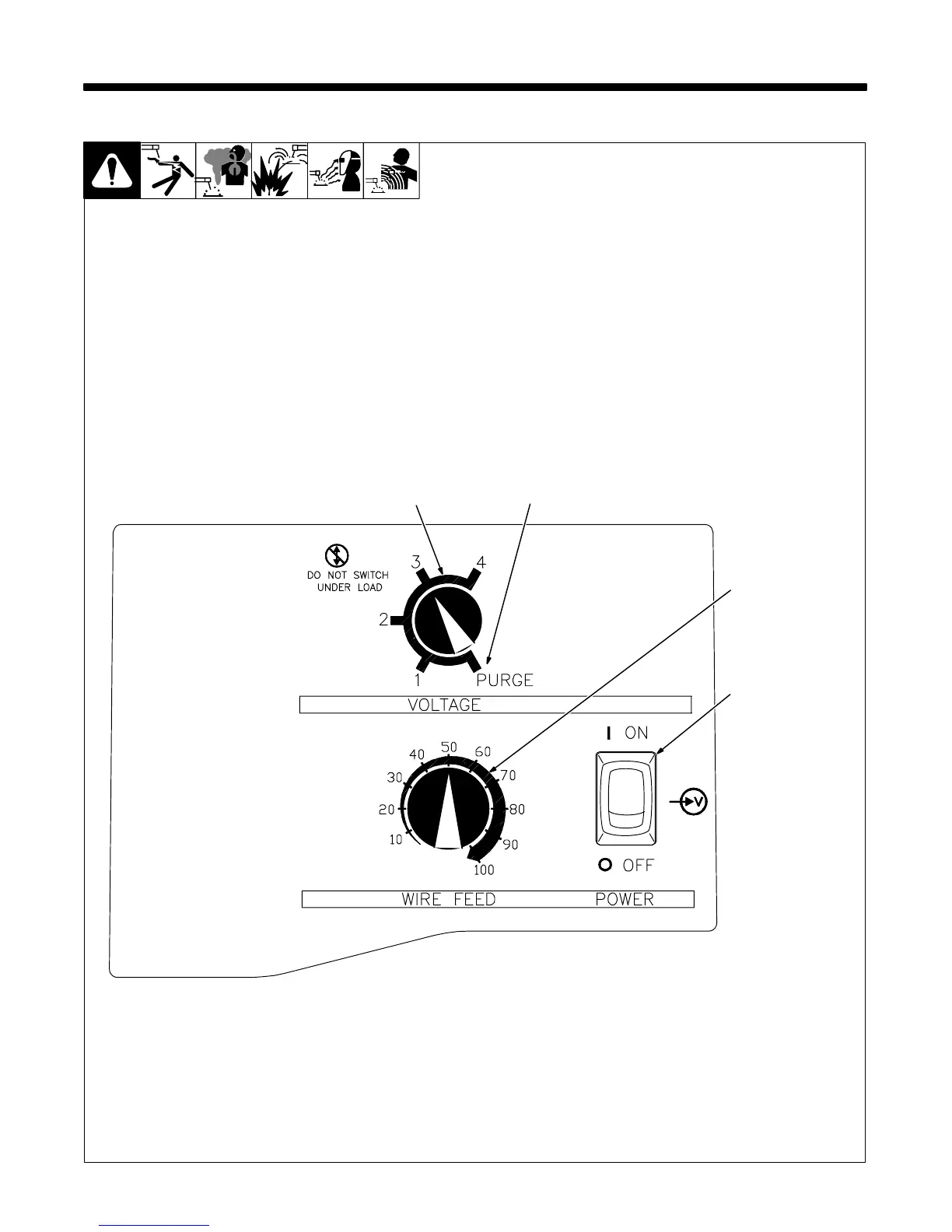
4-1. Controls
1 Voltage Switch
The higher the selected number,
the thicker the material that can be
welded (see weld setting label in
welding power source or Sections
4-2 and 4-3, as applicable). Do not
switch under load.
. Switch must “click” into detent
position 1, 2, 3, 4, or purge for
proper contact.
2 Voltage Switch - Purge “0”
Position
In purge position, fan runs but there
is no weld output.
3 Wire Speed Control
Use control to select a wire feed
speed. As Voltage switch setting in-
creases, wire speed range also in-
creases (see weld setting label in
welding power source or Sections
4-2 or 4-3, as applicable).
4 Power Switch
Ref. 196 082
2
1
3
4