EasyManuals Logo

Hobart Handler 140 Technical Manual

Hobart Handler 140
48 pages
To Next Page IconTo Next Page
To Previous Page IconTo Previous Page
Page #7 background imageLoading...
Page #7 background image
TM-258 267 Page 5Handler 140
SECTION 4 INSTALLATION
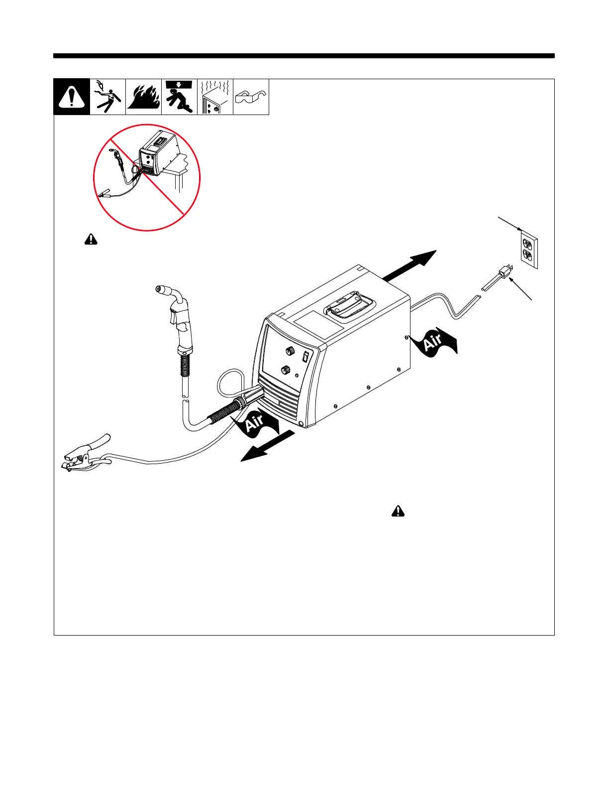
4-1. Selecting A Location
1 Plug From Unit 2 Grounded Receptacle
Locate unit near correct input power
supply.
! Special installation may be
required where gasoline or volatile
liquids are present see NEC
Article 511 or CEC Section 20.
2
258 641-A
! Do not move or operate unit
where it could tip.
1
18 in.
(460 mm)
18 in.
(460 mm)

Other manuals for Hobart Handler 140

Questions and Answers:

Question and Answer IconNeed help?

Do you have a question about the Hobart Handler 140 and is the answer not in the manual?

Hobart Handler 140 Specifications

General IconGeneral
Input Voltage115V
Welding Amperage Range25-140 A
Duty Cycle20% @ 90A
Wire Feed Speed Range40-700 IPM
Weldable MaterialsMild Steel, Stainless Steel, Aluminum
Weight57 lbs
ProcessesMIG (GMAW), Flux-Cored (FCAW)
Input Current20A
Welding Thickness24 ga. - 1/4 in.
Input PhaseSingle Phase
Maximum Open Circuit Voltage28V
Wire Size Range0.023 - 0.035 in

Related product manuals