TM-258 267 Page 25Handler 140
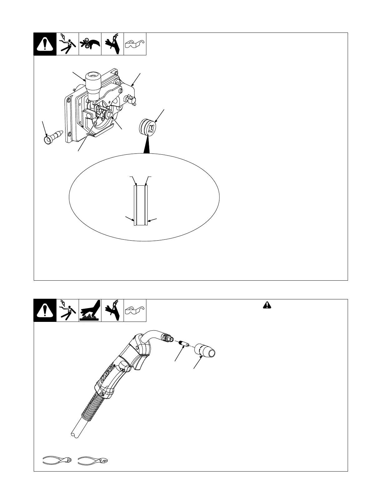
8-4. Changing Drive Roll Or Wire Inlet Guide
1 Inlet Wire Guide Securing Screw
2 Inlet Wire Guide
Loosen thumbscrew. Slide tip as close to
drive rolls as possible without touching.
Tighten thumbscrew.
3 Drive Roll
The drive roll consists of two different
grooves. The stamped markings on the end
surface of the drive roll refers to the groove
on the opposite side of the drive roll. The
groove closest to the motor shaft is the
proper groove to thread (see Section 4-11).
. VK (Knurled) groove is used for flux
cored wire and V groove is used for solid
wire.
4 Retaining Pin
To secure drive roll, locate open slot and
push drive roll completely over retaining pin,
then rotate drive roll (1/4 turn) to closed slot.
5 Drive Roll Tension Knob
Using flux core wire with VK groove, tension
should be set between 1-1/2 to 2. Higher
setting may cause welding wire to deform
and not allow proper feeding.
Flux Core Wire − Recommended stickout is
1/2 in. (12.7 mm) from gun tip.
Solid Wire − Recommended stickout is 3/8 in.
(9.5 mm) from gun tip.
Actual drive roll may differ from that
shown. See Section 11-3 for additional
drive roll configurations.
258 380-B
.030/.035 VK Groove
is used for Flux Core
(Gasless) Wire
.030/.035 V Groove
is used for Solid Wire
Stamped
.030/.035
VK Grooved
Stamped .030/.035 V
2
Example
4
1
3
5 . Be sure gun is fully inserted into drive
housing. Liner to drive roll distance
should be within 1/8 in. (3.2 mm). of
each other.
8-5. Replacing Gun Contact Tip
Ref. 246 669-A
! Turn Off power before
replacing contact tip.
1 Nozzle
2 Contact Tip
Cut off welding wire at contact tip.
Remove nozzle.
Remove contact tip and install new
contact tip. Reinstall nozzle.
Tools Needed:
1
2