TM-258 267 Page 16 Handler 140
1 Supplementary Protector CB1
Protects unit from an over-current
condition by opening primary power
line.
2 Power Switch S1
Turns unit and fan motor FM on and
off.
3 Contactor CR3
Turns weld output on and off.
Provides shielding gas flow when
CR3 is energized.
4 Fan Motor FM And Control
Transformer
Controlled by power switch S1. Fan
cools internal components, and
transformer supplies 24 volts AC to
PC1 control circuit.
5 Range Switch S2
Allows selection of a primary
winding tap which provides a weld
output voltage level.
6 Gas Valve GS1
Provides shielding gas flow when
CR3 is energized.
7 Control Board PC1
Switches weld output on and off by
controlling CR3. Regulates motor
speed at a percentage set with Wire
Speed control R2. Provides
dynamic motor braking and starting
through the motor relay. Provides a
bleeder resistor for capacitor C1.
8 Thermostat TP1
If main transformer overheats, TP1
opens gun switch circuit stopping
all weld output.
9 Gun Trigger Receptacle RC3
Connects gun trigger circuit to
welding power source.
10 Wire Speed Control R2
Sets a wire feed motor speed by
providing a reference voltage to
motor control circuit on PC1.
11 Wire Drive Motor
Feeds wire at a speed set by R2.
Wire drive circuit on PC1 receives
weld output voltage so that voltage
changes result in motor speed
changes.
12 Main Transformer T1
Supplies power to weld output
circuit.
13 Rectifier SR1
Changes the AC output from T1 to
full-wave rectified DC output.
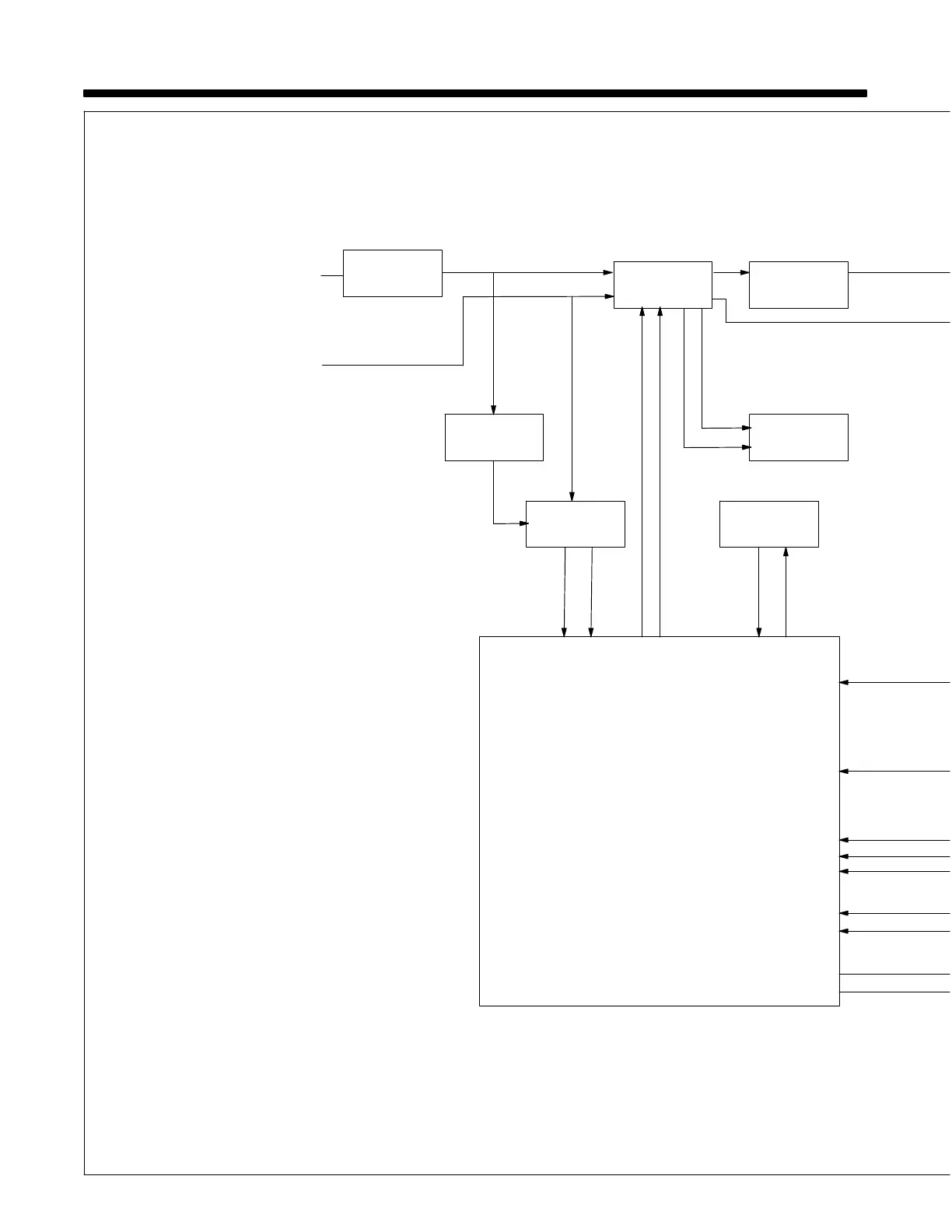
SECTION 6 − THEORY OF OPERATION
2
4
6
Single-Phase
Line Input
Power
1
Supplementary
Protector CB1
Power Switch
S1
Gas Valve
GS1
Line
L1
Neutral Line
(115 VAC Model)
Fan Motor FM
And Control
Transformer
Control Board
PC1
7
Line L2
(230 VAC Models)
3
Contactor CR3
5
Range Switch
S2
17
Over
Temperature
Light PL1