TM-258 267 Page 6 Handler 140
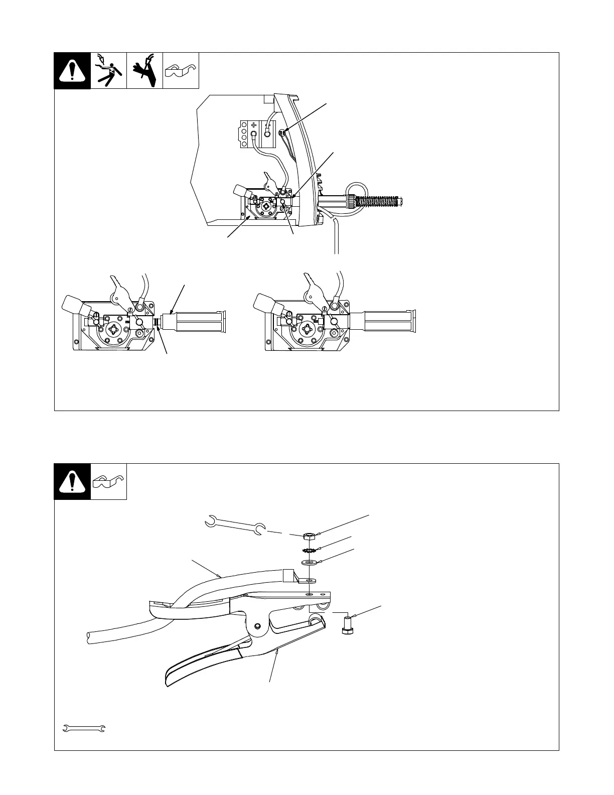
4-2. Installing Welding Gun
258 315-A
1 Drive Assembly
2 Gun Securing Thumbscrew
3 Gun End
Loosen thumbscrew. Insert end of
gun through opening in front
panel until it bottoms against
drive assembly. Tighten
thumbscrew.
Welding gun must be inserted
completely to prevent leakage of
shielding gas.
4 Gun Trigger Leads
Insert leads, one at a time, through
gun opening on front panel.
Connect female friction terminals to
matching male terminals in unit.
Polarity is not important.
Close door.
Correct
Incorrect
. Be sure that gun end is tight
against drive assembly.
Gun Fully Seated
3
Gun Not Seated
Exposed O-rings
will cause shielding
gas leakage.
4
1
2
3
4-3. Installing Work Clamp
1 Work Clamp
2 Work Cable From Unit
3 Screw
4 Flat Washer
5 Lock Washer
6 Nut
Route work cable through hole in
clamp handle. Secure cable with
hardware as shown.
258 550-A
. Connection hardware must be tightened with proper tools. Do not just
hand tighten hardware. A loose electrical connection will cause poor weld
performance and excessive heating of the work clamp.
Tools Needed:
10 mm
1
2
3
4
5
6