EasyManuals Logo

Hobart Handler 140 Technical Manual

Hobart Handler 140
48 pages
To Next Page IconTo Next Page
To Previous Page IconTo Previous Page
Page #11 background imageLoading...
Page #11 background image
TM-258 267 Page 9Handler 140
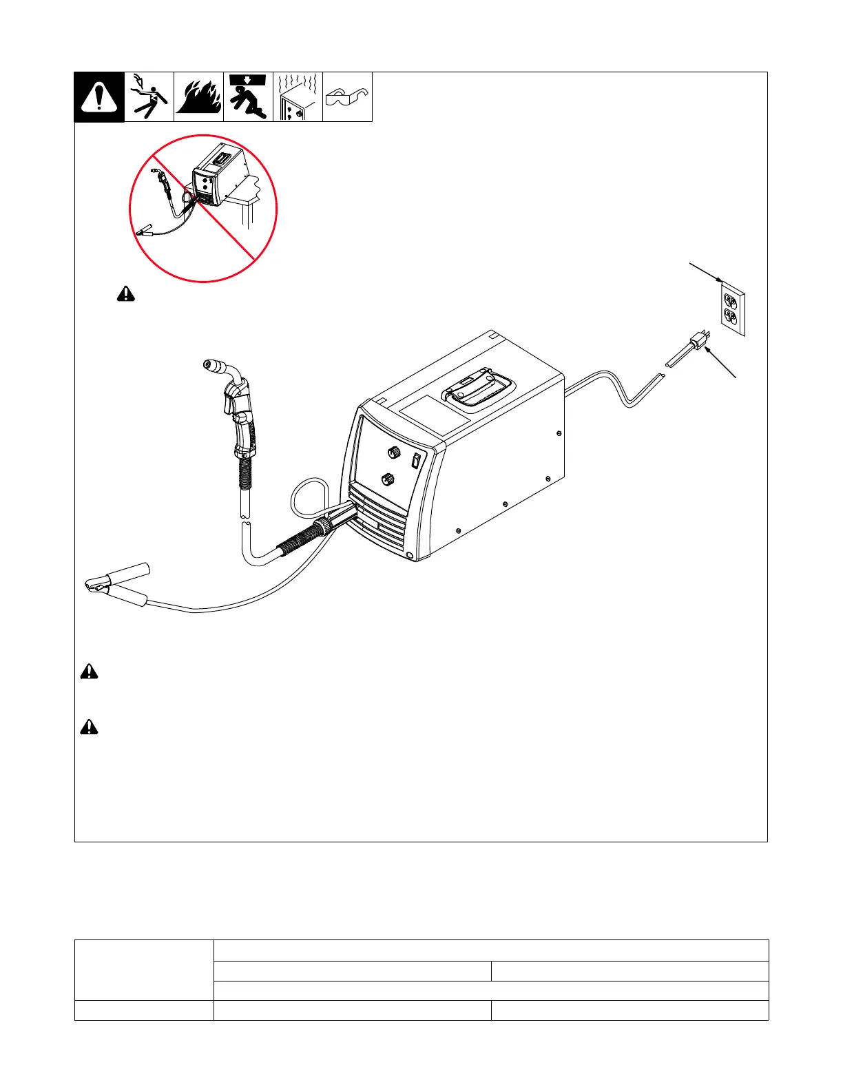
4-7. Connecting Input Power
! Installation must meet all National
and Local Codes have only
qualified persons make this
installation.
! Special installation may be
required where gasoline or volatile
liquids are present see NEC
Article 511 or CEC Section 20.
A 115 volts AC, 20 ampere individual circuit
protected by time-delay fuses or circuit
breaker is required.
1 Plug From Unit
2 Receptacle NEMA Type 515R
(Customer Supplied)
2
Input6 201103 258 641-A
! Do not move or operate unit
where it could tip.
1
4-8. Selecting Extension Cord (Use Shortest Cord Possible)
Single Phase AC
Input Voltage
Conductor Size AWG (mm
2
)*
10 (5.3) 12 (3.3)
Maximum Allowable Cord Length in ft (m)
115 100 (30.5) 50 (15.0)
*Conductor size is based on maximum 3% voltage drop

Other manuals for Hobart Handler 140

Questions and Answers:

Question and Answer IconNeed help?

Do you have a question about the Hobart Handler 140 and is the answer not in the manual?

Hobart Handler 140 Specifications

General IconGeneral
Input Voltage115V
Welding Amperage Range25-140 A
Duty Cycle20% @ 90A
Wire Feed Speed Range40-700 IPM
Weldable MaterialsMild Steel, Stainless Steel, Aluminum
Weight57 lbs
ProcessesMIG (GMAW), Flux-Cored (FCAW)
Input Current20A
Welding Thickness24 ga. - 1/4 in.
Input PhaseSingle Phase
Maximum Open Circuit Voltage28V
Wire Size Range0.023 - 0.035 in

Related product manuals