EasyManuals Logo

Hobart Handler 140 Technical Manual

Hobart Handler 140
48 pages
To Next Page IconTo Next Page
To Previous Page IconTo Previous Page
Page #31 background imageLoading...
Page #31 background image
TM-258 267 Page 29Handler 140
SECTION 9 ELECTRICAL DIAGRAMS
. The circuits in this manual can be used for troubleshooting, but there might be minor circuit differences from your machine. Use circuit inside
machine case or contact your distributor for further information.
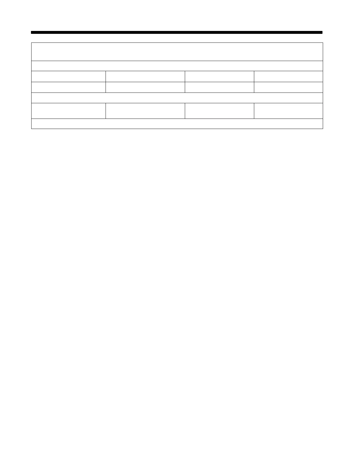
Model Serial Or Style Number Circuit Diagram Wiring Diagram
Welding Power Source MC370275YAnd following 257 502-A 257 500-A
Circuit Board PC1
(115 VAC Model)
MC370275Y and following 256 987-A 
Not included in this manual

Other manuals for Hobart Handler 140

Questions and Answers:

Question and Answer IconNeed help?

Do you have a question about the Hobart Handler 140 and is the answer not in the manual?

Hobart Handler 140 Specifications

General IconGeneral
Input Voltage115V
Welding Amperage Range25-140 A
Duty Cycle20% @ 90A
Wire Feed Speed Range40-700 IPM
Weldable MaterialsMild Steel, Stainless Steel, Aluminum
Weight57 lbs
ProcessesMIG (GMAW), Flux-Cored (FCAW)
Input Current20A
Welding Thickness24 ga. - 1/4 in.
Input PhaseSingle Phase
Maximum Open Circuit Voltage28V
Wire Size Range0.023 - 0.035 in

Related product manuals