EasyManuals Logo

Hobart Handler 140 Technical Manual

Hobart Handler 140
48 pages
To Next Page IconTo Next Page
To Previous Page IconTo Previous Page
Page #13 background imageLoading...
Page #13 background image
TM-258 267 Page 11Handler 140
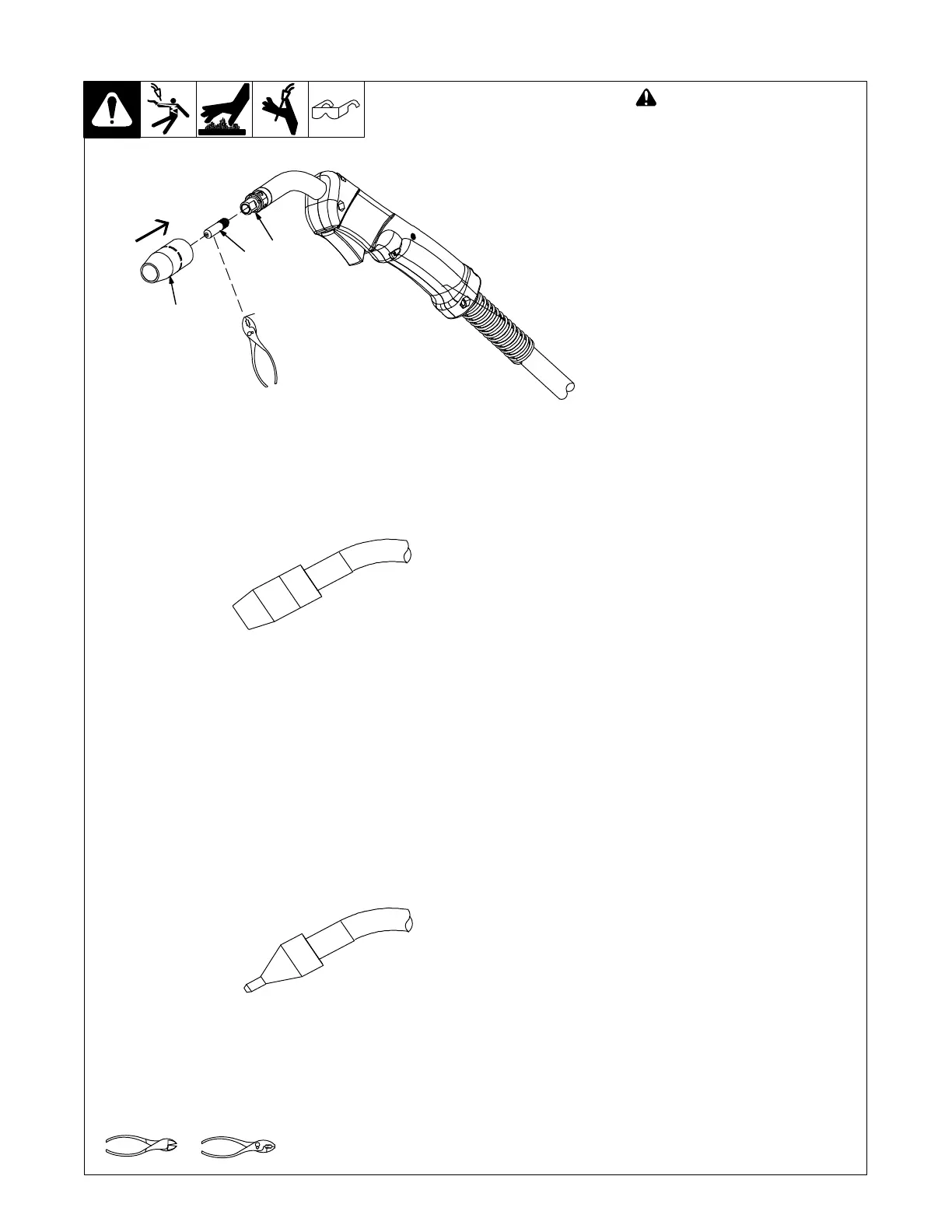
4-10. Installing Contact Tip And Nozzle
Tools Needed:
Ref. 246 669-A
! Turn off welding power source.
1 Nozzle
Remove nozzle.
2 Contact Tip
3 Tip Adapter
Thread welding wire through gun (see
Section 4-11).
Slide contact tip over wire and tighten
tip into tip adapter.
Install nozzle.
Flux Nozzle (Optional)
MIG Nozzle (Standard)
Use with flux cored wire only.
Narrow design allows access in
tight spaces and provides better
visibility of puddle during welding.
Use with solid or flux cored wire.
Push nozzle over contact tip and
adapter until it is seated onto
adapter. Contact tip will be
exposed approximately 7/16 in.
(11.3 mm) when installed properly.
Push nozzle over contact tip and
adapter until it is seated onto
adapter. End of contact tip will be
flush with end of nozzle when
installed properly.
1
2
3

Other manuals for Hobart Handler 140

Questions and Answers:

Question and Answer IconNeed help?

Do you have a question about the Hobart Handler 140 and is the answer not in the manual?

Hobart Handler 140 Specifications

General IconGeneral
Input Voltage115V
Welding Amperage Range25-140 A
Duty Cycle20% @ 90A
Wire Feed Speed Range40-700 IPM
Weldable MaterialsMild Steel, Stainless Steel, Aluminum
Weight57 lbs
ProcessesMIG (GMAW), Flux-Cored (FCAW)
Input Current20A
Welding Thickness24 ga. - 1/4 in.
Input PhaseSingle Phase
Maximum Open Circuit Voltage28V
Wire Size Range0.023 - 0.035 in

Related product manuals