TM-258 267 Page 23Handler 140
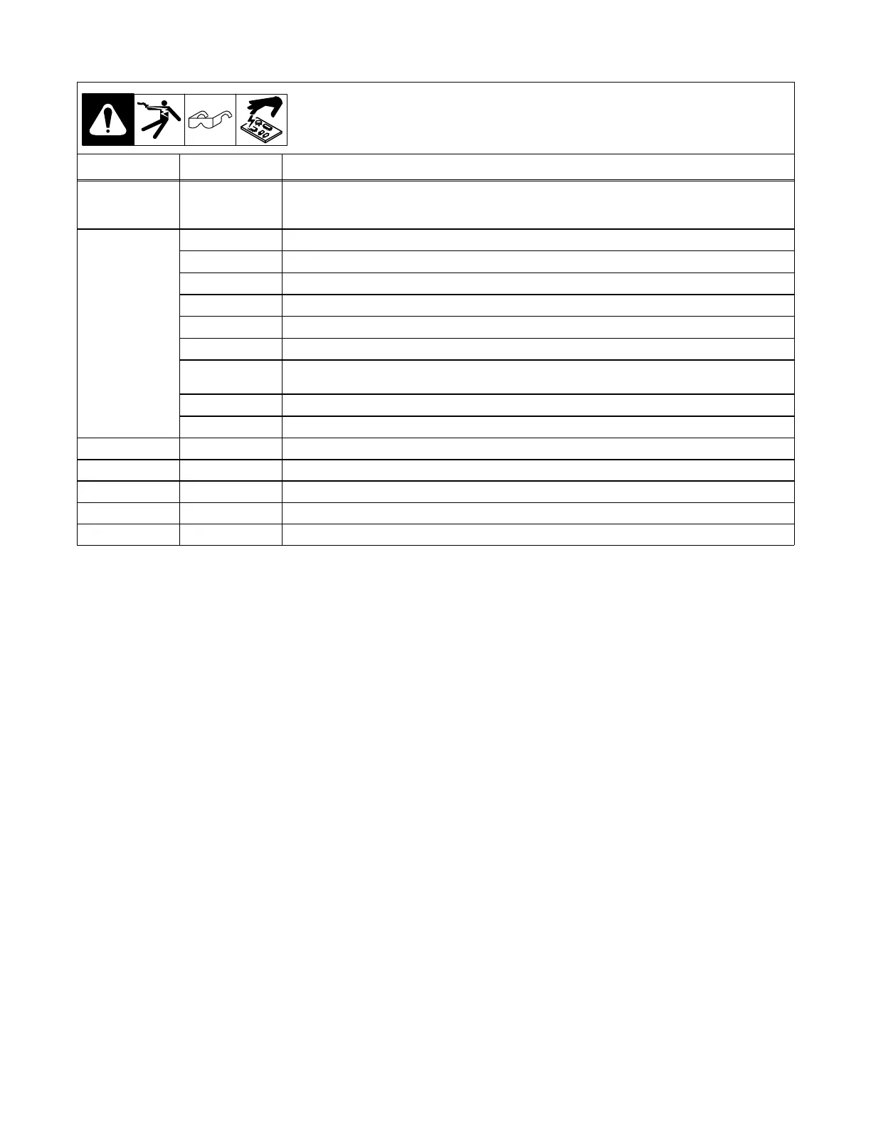
7-4. Control Board PC1 Test Point Values
PC1 Voltage Readings
a) Tolerance −
10% unless
specified
b) Reference − as noted
Receptacle Pin Value
RC1 1 − 2 0 volts DC with gun trigger open Voltage switch S2 in position 5
5.6 volts DC with Wire Speed control R2 set to min. and gun trigger closed
23.6 volts DC with Wire Speed control R2 set to max. and gun trigger closed
RC2
1 30 volts DC, reference to Pin 5
2 30 volts DC, reference to Pin 5, gun trigger closed
3 30 volts DC, reference to Pin 5
4 29 volts DC, reference to Pin 5, gun trigger closed
5 Circuit common
6 27 volts DC, reference to Pin 5, gun trigger closed
7 27 volts DC with Wire Speed control R2 at maximum, reference to Pin 5
6.3 volts DC with Wire Speed control R2 at minimum, reference to Pin 5
8 Not used
9 − 10 24 volts AC with gun trigger open
11 − 12 24 volts AC with gun trigger closed
13 29 volts DC, reference to Pin 5
14 29 volts DC, reference to Pin 5
15 29 volts DC, reference to Pin 5
16 Not used