EasyManuals Logo

Hobart Handler 140 Technical Manual

Hobart Handler 140
48 pages
To Next Page IconTo Next Page
To Previous Page IconTo Previous Page
Page #19 background imageLoading...
Page #19 background image
TM-258 267 Page 17Handler 140
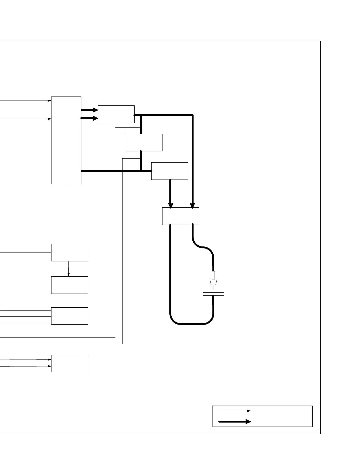
AC Or DC Control Circuits
Weld Current Circuit
Welding Wire
Work
14
(Electrode)
12
Main
Transformer
T1
13
Rectifier SR1
15
Stablizer L1
Capacitor C1
16
Polarity
Changeover
Block
Wire Drive
Motor
11
8
9
Thermostat
TP1
Gun Trigger
Receptacle RC3
10
Wire Speed
Control R2
14 Output Capacitor C1
Smooths DC weld voltage from
rectifier SR1.
15 Stabilizer L1
Smooths DC weld current.
16 Polarity Changeover Block
Terminals allow changing between
DCEP and DCEN processes.
17 Over Temperature Light PL1
Indicates that the transformer is
overheated.

Other manuals for Hobart Handler 140

Questions and Answers:

Question and Answer IconNeed help?

Do you have a question about the Hobart Handler 140 and is the answer not in the manual?

Hobart Handler 140 Specifications

General IconGeneral
Input Voltage115V
Welding Amperage Range25-140 A
Duty Cycle20% @ 90A
Wire Feed Speed Range40-700 IPM
Weldable MaterialsMild Steel, Stainless Steel, Aluminum
Weight57 lbs
ProcessesMIG (GMAW), Flux-Cored (FCAW)
Input Current20A
Welding Thickness24 ga. - 1/4 in.
Input PhaseSingle Phase
Maximum Open Circuit Voltage28V
Wire Size Range0.023 - 0.035 in

Related product manuals