EasyManua.ls Logo

Hobart Handler 140 - User Manual

Hobart Handler 140
48 pages
Print Icon
To Next Page IconTo Next Page
Loading...
Processes
OM-925 217 694F
201004
Handler 140
And H-10 Gun
Arc Welding Power Source And
Wire Feeder
Description
MIG (GMAW) Welding
Flux Cored (FCAW) Welding
R

Table of Contents

Other manuals for Hobart Handler 140

Questions and Answers

  • M
    Michelle NewmanNov 16, 2025
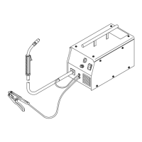
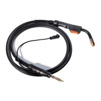
    What to do if there is no weld output and wire feed, but the fan runs on my Hobart Welding System?
    • M
      mowensNov 17, 2025
      If your Hobart Welding System isn't providing weld output, and the wire isn't feeding but the fan is running, here are some things to check: * Ensure the Voltage switch S2 is correctly positioned. Rotate the knob until it clicks into place at the desired range setting. * Make sure the gun trigger leads are securely connected to receptacle RC3. * Check the continuity of the gun trigger leads, and repair or replace the gun if needed. * Inspect the Voltage switch S2 for continuity, and replace it if necessary. * Examine the diodes in the main rectifier SR1, and replace them if necessary. * Look for signs of winding failure in the main transformer T1. Check the continuity across windings, ensure proper connections, and check secondary voltages. Replace T1 if necessary. * Check t...
  • J
    Joseph JonesNov 19, 2025
    Why does the electrode wire feeding stop during welding with my Hobart Handler 140?
    • S
      Sarah MillerNov 19, 2025
      If your Hobart Welding System's electrode wire stops feeding during welding, consider the following: * Straighten the gun cable or replace any damaged parts. * Readjust the drive roll pressure. * Change to the proper drive roll groove. * Readjust the wire reel hub tension. * Replace the contact tip if it's blocked. * Clean or replace the wire inlet guide or liner if they're dirty or plugged. * Replace the drive roll or pressure bearing if they're worn or slipping. * Secure the gun trigger leads in receptacle RC3. * Check the continuity of the gun trigger leads and repair or replace the gun if necessary. * Check and clear any restrictions at the drive assembly and liner. * Release the gun trigger and allow the gun and motor protection circuitry to reset. * Check T1 ...

Summary

Safety Precautions

Symbol Usage and Arc Welding Hazards

Explains manual symbols and details arc welding risks.

Key Hazard Categories

Summarizes fumes, gases, arc rays, fire, explosion, and cylinder safety.

California Proposition 65 Warnings

Details chemical warnings mandated by California law for engines and products.

Principal Safety Standards and EMF Information

Lists safety standards and EMF precautions for medical implants.

Definitions

Symbols And Definitions

Defines symbols used in the manual for electrical and welding processes.

Specifications

General Specifications

Provides technical specifications for the welding unit, including output and dimensions.

Duty Cycle And Overheating

Explains duty cycle limitations and overheating indicators and actions.

Volt-Ampere Curves

Illustrates voltage and amperage output capabilities for different settings.

Installation

Gun and Work Clamp Installation

Guides for attaching the welding gun and work clamp for proper operation.

Polarity and Gas Supply Setup

Details process polarity and installing the shielding gas supply.

Unit Setup and Wire Spool Installation

Covers location, power connection, serial number, and wire spool setup.

Wire Feeding System Setup

Instructions for installing tips, nozzles, and threading welding wire.

Operation

Controls Overview

Identifies and explains the functions of the welding unit's control panel.

Weld Parameter Chart

Provides recommended settings for voltage and wire speed based on material and wire type.

Maintenance & Troubleshooting

Routine Maintenance Procedures

Covers maintenance of overload protection, drive motor, and routine checks.

Gun Component Replacement

Guides for replacing drive rolls, contact tips, and gun liners.

Troubleshooting Common MIG Issues

Addresses problems like spatter, porosity, penetration, fusion, and burn-through.

Electrical Diagram

Circuit Diagram

Provides the detailed circuit diagram for the welding power source.

MIG Welding (GMAW) Guidelines

MIG Process Connections and Settings

Illustrates MIG setup, connections, and control settings for optimal welding.

Gun Handling and Weld Bead Characteristics

Explains gun positioning and factors affecting weld bead shape and quality.

Troubleshooting Common MIG Welding Issues

Provides solutions for spatter, porosity, penetration, fusion, and burn-through problems.

Shielding Gases and Equipment Troubleshooting

Covers common shielding gases and a guide for semiautomatic welding equipment issues.

Accessories;Consumables

Accessories and Consumables

Lists available accessories, consumables like tips and nozzles, and replacement parts.

Drive Rolls and Regulators

Details replacement drive rolls and regulator/flowmeter options for gas supply.

Warranty Information

Limited Warranty Terms and Exclusions

Details the 5/3/1 warranty, its coverage, exclusions, and intended use.

Warranty Claims and Legal Disclaimers

Outlines warranty claim procedures, remedies, and legal limitations.

Owners Record and Resources

Personal Records and Registration

Section to record purchase details and register the product for protection.

Distributor and Technical Assistance

Information on locating distributors, obtaining technical help, and ordering parts.

Hobart Handler 140 Specifications

General IconGeneral
Input Voltage115V
Welding Amperage Range25-140 A
Duty Cycle20% @ 90A
Wire Feed Speed Range40-700 IPM
Weldable MaterialsMild Steel, Stainless Steel, Aluminum
Weight57 lbs
ProcessesMIG (GMAW), Flux-Cored (FCAW)
Input Current20A
Welding Thickness24 ga. - 1/4 in.
Input PhaseSingle Phase
Maximum Open Circuit Voltage28V
Wire Size Range0.023 - 0.035 in

Related product manuals