TM-260 273 Page 43Handler 190
258 389-A
1
2
3
4
5
6
14
8
7
11
9
12
13
10
15
16
17
18
19
20
21
22
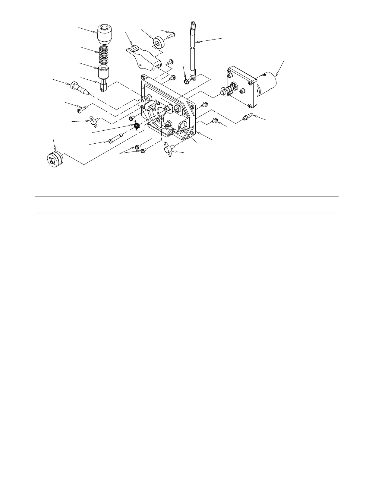
Figure 9-2. Wire Feed Drive Assembly
Description
Part
No.
Dia.
Mkgs.
258 389
Item
No.
Figure 9-2. Wire Feed Drive Assembly
Quantity
1 256 956 Cover, Motor Drive 1... ............... .. .............................................
2 257 420 Housing, Wire Drive 1... ............... .. ............................................
3 257 422 Lever,Mtg Pressure Gear 1... ............... .. ........................................
4 189 915 Bearing, Ball 1... ............... .. ...................................................
5 176 869 Screw, 010−32 x 0.62 1... ............... .. ...........................................
6 203 418 Spring, Torsion 1... ............... .. .................................................
7 257 790 Screw, .250−28 x .953 Shld .1... ............... .. ......................................
8 082 193 Screw, 010−32 x 0.37 hex hd .4... ............... .. ....................................
9 197 172 Screw, 006−32 x 0.37 3... ............... .. ...........................................
10 196 895 Knob,Tension 1... ............... .. ..................................................
11 234 200 Spring, Compression 1... ............... .. ...........................................
12 196 896 Cup, Spring Tension 1... ............... .. ............................................
13 225 718 Fastener, Pinned 1... ............... .. ...............................................
14 257 792 Screw, Shld Stl 10−32 x .60 1... ............... .. .....................................
15 256 960 Guide, Inlet .023−.052 1... ............... .. ..........................................
16 257 865 Knob,T 1.00 Bar W/10−32 x .375 1... ............... .. .................................
17 246 565 Roll, Drive V/VK Groove .030−.035 1... ............... .. ...............................
18 217 778 Motor, Gear 1... ............... .. ...................................................
19 230 012 Fitting, Gas 1... ............... .. ....................................................
20 196 109 Cable 1... ............... .. .........................................................
21 602 154 Screw, .250−20 x .50 1... ............... .. ...........................................
22 257 864 Knob, T 1.265 Bar w/.250-20 Stud .625 Lg Plstc 1... ............... .. ....................
To maintain the factory original performance of your equipment, use only Manufacturer’s Suggested
Replacement Parts. Model and serial number required when ordering parts from your local distributor.