Discovery QDR Series Technical Manual
5-28
Install the ASY-00271 Detector Assembly
1. Install the ASY-00271 Detector Assembly (see Figure 5-13) in place of the 010-
1653 using the screws removed in Step 3.
2. Connect the 180-0292 laser cable.
3. Re-route the 180-0419 ribbon cable and install it on P1 of the ASY-00271.
4. Install the 370-0056 clamp-on ferrite core over the 180-0419 ribbon cable.
5. Turn on the Discovery power, boot the computer and login as Service.
6. Perform “X-Ray Beam Alignment ” on page 4-4.
7. Perform “A/D Gain Control Adjustment” on page 4-26.
8. Perform “Laser Positioning Offset Adjustment” on page 4-26.
9. Replace any covers that were removed and perform “Detector Flattening ” on
page 4-29.
10. Perform the Field Service Calibration procedure.
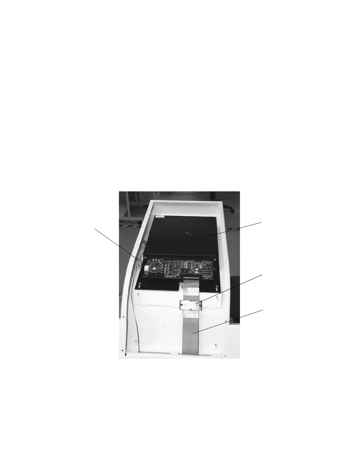
Figure 5-13. Detector Assembly ASY-00271
11. Perform a System Backup.
12. Perform a System Recover. Verify that the System Backup recovers without error.
13. Verify proper system operation.
ASY-00271
370-0056
180-0419
180-0292
laser cable