Discovery QDR Series Technical Manual
3-20
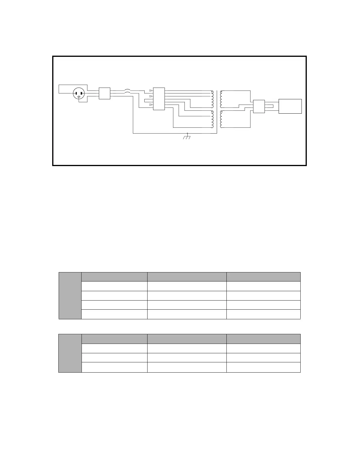
7. Attach the ground wire to the grounding lug using the hardware provided. Attach
the neutral and phase wires to TB1.
8. Install the circuit breaker from the voltage kit into the hole in the rear of the Tor-
roid Assembly using the screws provided in the kit
9. Attach the two wires (brown and blue) from TB1 to the Line terminals (top ter-
minals) on the circuit breaker.
10. Attach the two wires (brown and blue) from TB2 to the Load terminals (bottom
terminals) on the circuit breaker.
11. Use the jumpers provided to configure the terminal block as shown in the tables
below.
Circuit Breaker = 310-0006 (7.5 Amp, 2 Pole)
Power Cable = 180-0622
120 VAC
50/60 Hz
Wire From To
Blue Circuit Breaker - Load Pin 1 – TB2
Brown Circuit Breaker – Load Pin 7 – TB2
Blue Jumper Pin 1 – TB2 Pin 4 – TB2
Brown Jumper Pin 3 – TB2 Pin 7 – TB2
230 VAC
50/60 Hz
Wire From To
Blue Circuit Breaker - Load Pin 1 – TB2
Brown Circuit Breaker – Load Pin 6 – TB2
Brown Jumper Pin 3 – TB2 Pin 4 – TB2
TB3
Filter Input
Brown
Blue
Blue
Black
44
33
22
11
TB2
Transformer Power
77
66
55
44
33
22
11
CB1
CIRCUIT BREAKER
Brown
T1
TRANSFORMER
Yellow
Orange
Red
Brown
Wht/Blu-0 VAC
Wht/Blk-120 VAC
Blue-0 VAC
Black-120 VAC
Brown-100 VAC
Red-110 VAC
Wht/Brn-100 VAC
Grn/Yel
AC Line Filter
230 VAC OPTION
1 (Brass) 2
3
Blue
240 VAC
TB1
Input Power
Black Brown
Whire Blue
Green Grn/Yel
LL
NN
GG