Discovery QDR Series Technical Manual
3-21
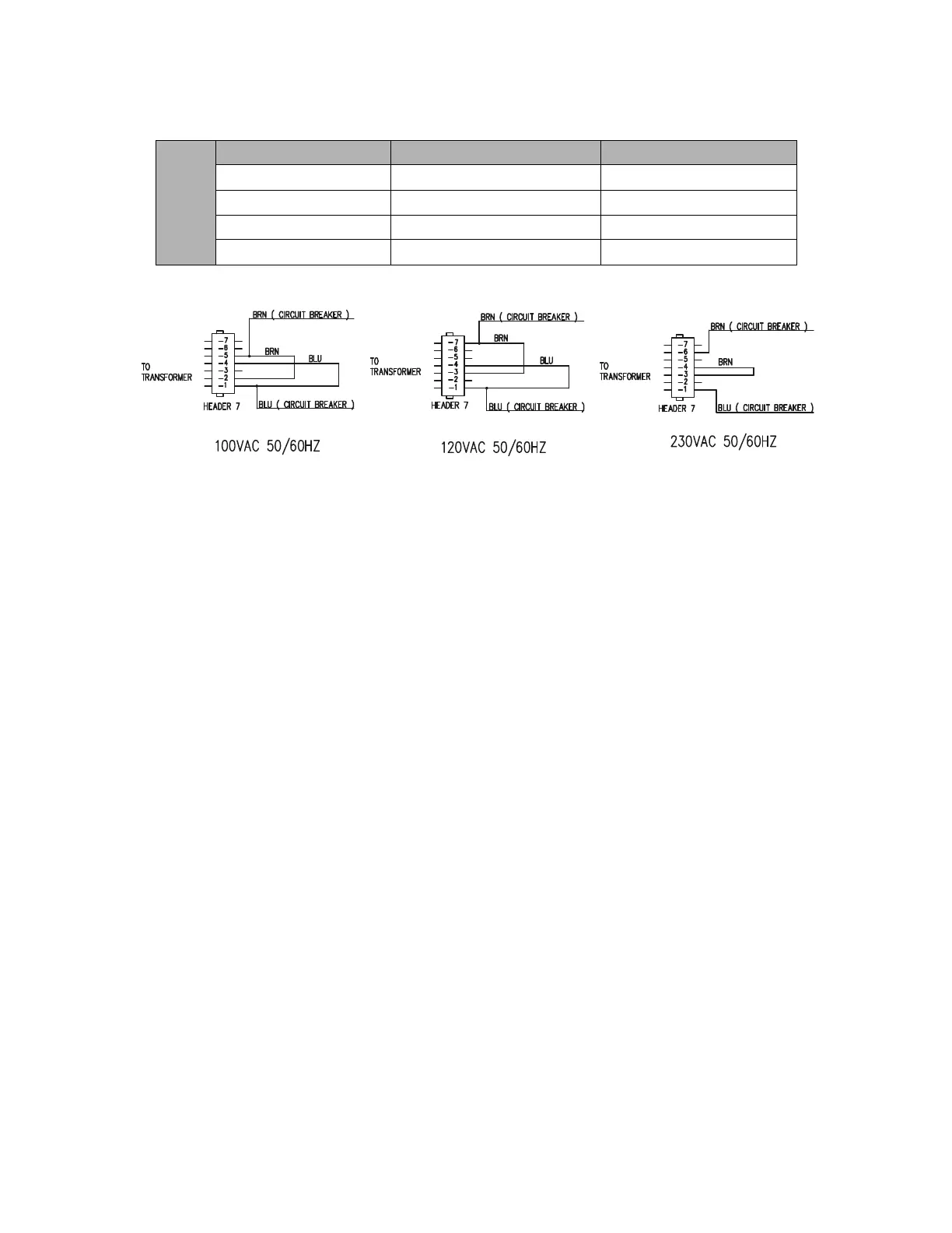
Figure 3-21. Isolation Transformer Input Taps
12. Confirm that the secondary side taps are set up as shown in the diagram in
Figure 3-21. These diagrams can also be found on the inside of the Torroid
Assembly Cover.
Note: The terminology “Header 7” used on Figure 3-21, and on the inside of the
Torroid Assembly Cover, comes from the schematic for the assembly (it is
a 7-pin terminal block “header”). The tables above refer to the same
terminal block as TB2 (the designation on the assembly drawing).
13. Replace the cover of the Torroid Assembly.
14. Route the Operator Console AC Supply Cable through the cable clamp block on
the rear of the Scanner.
15. Attach the Console Power Cord to the top power receptacle. The bottom power
receptacle is used in the manufacturing process to power a light when X-rays are
on. The bottom receptacle can be used to power an external x-ray on annunciator
lamp at the customer site (if required by local regulations).
16. Route the Operator Console Communications Cable through the cable clamp
block on the rear of the Scanner.
100 VAC
50/60 Hz
Wire From To
Blue Circuit Breaker - Load Pin 1 – TB2
Brown Circuit Breaker – Load Pin 5 – TB2
Blue Jumper Pin 1 – TB2 Pin 4 – TB2
Brown Jumper Pin 2 – TB2 Pin 5 – TB2