Discovery QDR Series Technical Manual
2-22
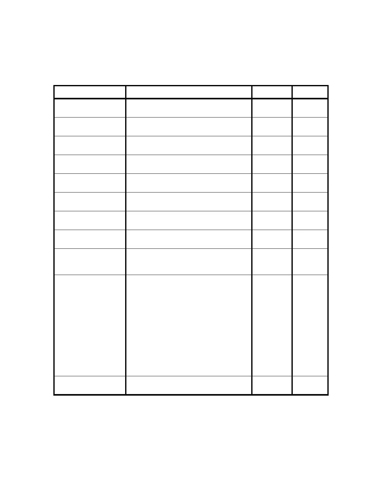
Figure 2-9. C-Arm Interface Board/128-Channel Detector Assembly
Interconnection Diagram
Table 2-13. C-Arm Interface Board/128-Channel Detector Assembly
Interconnection Descriptions
Notes: 1.C-Arm = C-Arm Interface Board
2.DA=128-Channel Detector Assembly
Signal Description
C-Arm
1
Pin DA
2
Pin
STD+
STD-
Synchronous data to the Analog/Digital
Converter board.
JP10-3
JP10-4
P1-12
P1-13
STCLK+
STCLK-
Synchronizes data to the Analog/Digital
Converter board.
JP10-6
JP10-7
P1-15
P1-16
STFRM+
STFRM-
Synchronizes DSP Communications. JP10-9
JP10-10
P1-18
P1-19
SRD+
SRD-
Synchronous Data from the Analog/Digital
board.
JP10-12
JP10-13
P1-3
P1-4
SRCLK+
SRCLK-
Synchronizes data from the Analog/Digital
Converter board.
JP10-15
JP10-16
P1-6
P1-7
SRFRM+
SRFRM-
Synchronizes DSP Communications. JP10-18
JP10-19
P1-9
P1-10
SYSRST_DAS+
SYSRST_DAS-
Resets the Analog/Digital Converter board. JP10-21
JP10-22
P1-21
P1-22
INTEGRATE+
INTEGRATE-
Data integration signal. Generated by the C-
Arm Interface Board.
JP10-24
JP10-25
P1-24
P1-25
XR_ZEROX_DAS+
XR_ZEROX_DAS-
AC line zero-crossing signal used for system
wide synchronization. Generated by the C-Arm
Interface Board.
JP10-27
JP10-28
P1-27
P1-28
+15V
-15V
15V_RET
+7V
Powers the Data Acquisition System.
JP10-32
JP10-33
JP10-36
JP10-37
JP10-30
JP10-31
JP10-34
JP10-35
JP10-38
JP10-39
P1-32
P1-33
P1-36
P1-37
P1-30
P1-31
P1-34
P1-35
P1-38
P1-39
CONTINUITY Emergency shutdown daisy chain (grounded on
ADC board)
JP10-1 P1-1