Discovery QDR Series Technical Manual
3-19
3. Measure the voltage between ground and neutral at the wall outlet that will be
used for the system. If it is more than TBD mV call Hologic Technical Support
before continuing.
4. Remove foot end cover on the Electronics Tray (on the left side facing the
machine) and the cover of the Torroid Assembly.
5. Remove the AC input cable from the kit, install the strain relief, and route the
cable though bottom of the Torroid Assembly.
6. Screw the strain relief into the bushing at the bottom of the Torroid Assembly and
fix the cable to the exposed stud using the cable clamp and NyLock nut provided
in the kit.
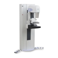
Circuit Breaker = 310-0018 (20 Amp, 2 Pole)
Power Cable = 180-0626
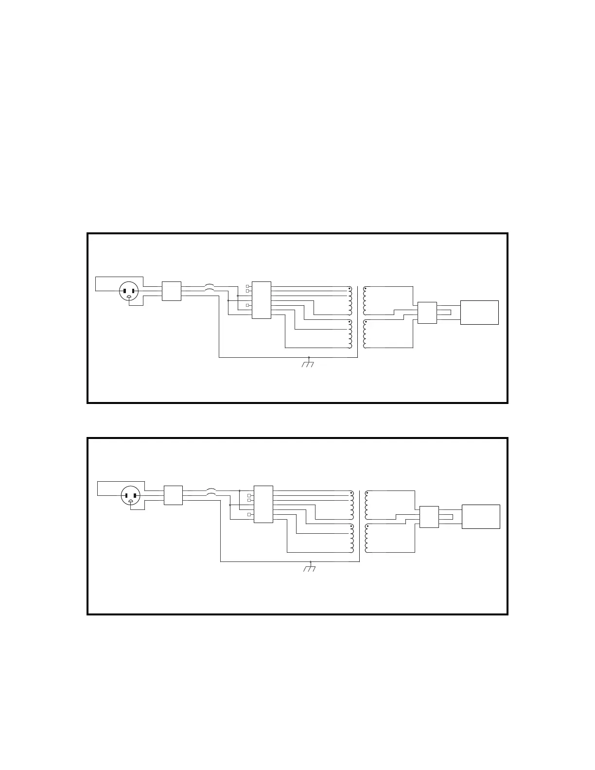
Circuit Breaker = 310-0053 (15 Amp, 2 Pole)
Power Cable = 180-0621
TB1
Input Power
Black Brown
Whire Blue
Green Grn/Yel
LL
NN
GG
TB2
Transformer Power
77
66
55
44
33
22
11
100 VAC OPTION
CB1
CIRCUIT BREAKER
Brown
Blue1 (Brass) 2
3
AC Line Filter
240 VAC
TB3
Filter Input
Brown
Blue
Blue
Black
44
33
22
11
T1
TRANSFORMER
Yellow
Orange
Red
Brown
Wht/Blu-0 VAC
Wht/Blk-120 VAC
Blue-0 VAC
Black-120 VAC
Brown-100 VAC
Red-110 VAC
Wht/Brn-100 VAC
Grn/Yel
1 (Brass) 2
3
TB2
Transformer Power
77
66
55
44
33
22
11
T1
TRANSFORMER
Yellow
Orange
Red
Brown
Wht/Blu-0 VAC
Wht/Blk-120 VAC
Blue-0 VAC
Black-120 VAC
Brown-100 VAC
Red-110 VAC
Wht/Brn-100 VAC
Grn/Yel
120 VAC OPTION
240 VAC
AC Line Filter
TB3
Filter Input
Brown
Blue
Blue
Black
44
33
22
11
CB1
CIRCUIT BREAKER
Brown
Blue
TB1
Input Power
Black Brown
Whire Blue
Green Grn/Yel
LL
NN
GG