Rev. 1.30 9 of 34 November 13, 2020
e-Link32/e-Link32 Pro User’s Guide
1 Overview
1 Overview
Dynamically Switching Power Conguration
Users can connect a switch on J4 to dynamically select the following power congurations.
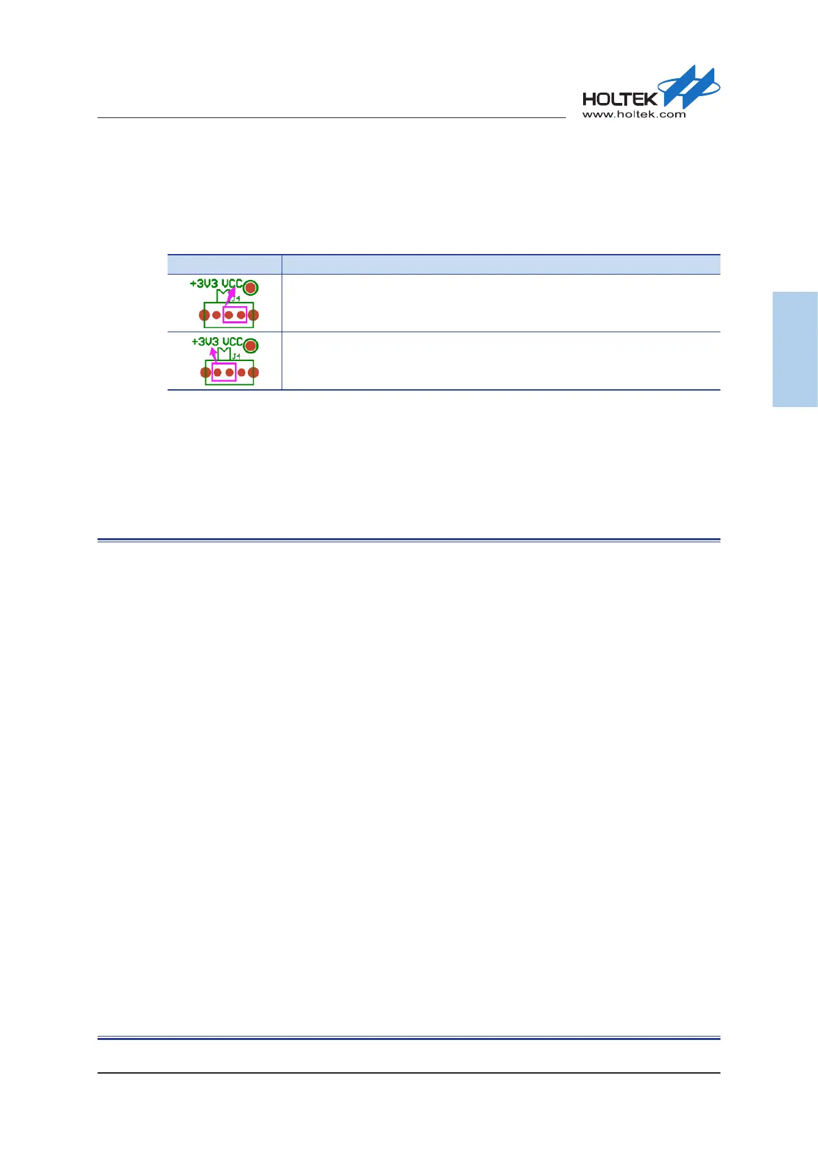
Table 5. Power Supply Switch – J4
J4 Description
SWD/RESET/UART interface voltage determined by the target board power supply
Target board power supply provided by the e-Link32/e-Link32 Pro
e-Link32/e-Link32 Pro Schematic Diagram
This section shows the entire e-Link32 and e-Link32 Pro circuit diagrams.
▄
e-Link32 v1.0
▄
e-Link32 Pro v1.0 (HT32F1654)
▄
e-Link32 Pro v1.0 (HT32F52341)