
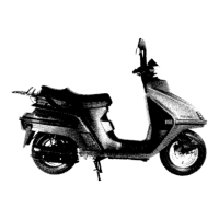
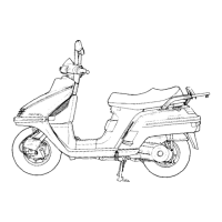
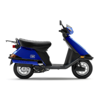
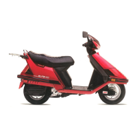
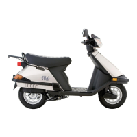
Do you have a question about the Honda CH250 Elite 1986 and is the answer not in the manual?
| Engine Type | Single-cylinder, four-stroke |
|---|---|
| Displacement | 244 cc |
| Bore x Stroke | 72.0 mm x 60.0 mm |
| Compression Ratio | 10.0:1 |
| Fuel System | Carburetor |
| Ignition | CDI |
| Starting System | Electric |
| Transmission | Automatic |
| Final Drive | V-Belt |
| Front Suspension | Telescopic fork |
| Rear Brake | Drum |
| Front Tire | 3.50-10 |
| Seat Height | 760 mm |
| Cooling System | Liquid-cooled |
Procedures for checking and changing engine oil, including capacity and filter cleaning.
Procedures for checking and changing transmission oil, including capacity and torque specifications.
Recommended maintenance intervals and tasks for the '85 model.
Recommended maintenance intervals and tasks for models after '85.
How to check brake shoe wear and determine when replacement is needed.
Checking tire pressure, condition, and recommended tire sizes.
Disassembly of the carburetor float chamber, float valve, and jets.
Procedure for measuring and adjusting the float level using a gauge.
Detailed procedure for adjusting the pilot screw for optimal idle and performance.
Procedures for safely removing the engine from the scooter frame.
Removing brake cables, shock absorbers, and engine mounting bolts for engine removal.
Steps for reinstalling the engine into the scooter frame.
Steps for removing the cylinder head, including thermostat case and bolts.
Compressing valve springs and disassembling the cylinder head, including valve cotters and stem seals.
Inspecting valve seats and refacing them using grinding tools for proper sealing.
Using various cutters to grind valve seats to the correct width and smoothness.
Assembling the cylinder head, installing valves, springs, and cotters.
Installing the cylinder head onto the engine block with proper gasket and torque.
Installing the camshaft, timing marks, cam chain, and tensioner.
Steps for removing the cylinder, including disconnecting water hose and bolts.
Procedures for removing the piston from the cylinder, including pin clip removal.
Measuring connecting rod end I.D., removing piston rings, and measuring ring end gap.
Correctly installing piston rings onto the piston, staggering end gaps.
Installing the piston and piston pin, ensuring correct orientation.
Installing the cylinder assembly, including dowel pins, gasket, and cam chain guide.
Steps for removing, inspecting, and installing the drive belt, including width measurement.
Removing the clutch/driven pulley assembly, checking clutch outer ID, and lining thickness.
Assembling the clutch components, including damper rubbers, clutch weights, and springs.
Assembling the driven pulley, including oil seals, O-rings, guide rollers, and pins.
Steps for disassembling the final reduction unit, including removing covers and gears.
Inspecting gears, shafts, and bearings for wear or damage.
Installing drive and final shaft bearings into the crankcase and transmission cover.
Assembling the final reduction unit, installing gears, shafts, and transmission cover.
Removing the flywheel, including oil orifice, drive pin, and nut.
Inspecting starter driven gear and idle gear for wear or damage, and checking clutch operation.
Installing the flywheel, woodruff key, and flywheel nut with correct torque.
Torque value for the crankcase bolts.
Steps for separating the crankcase halves, including removing tensioner, bolts, and cam chain.
Inspecting the crankshaft for wear, damage, and measuring connecting rod end clearances and runout.
Assembling the crankcase, including applying grease to new oil seals.
Installing heat insulator, crankcase bolts, cam chain, and tensioner slipper.
Procedure for draining, replacing, and bleeding the cooling system coolant.
Inspecting the water pump mechanical seal and removing the pump assembly.
Removing and inspecting the front wheel, including axle shaft, rim, and bearings.
Removing and inspecting the front brake drum, linings, and brake shoes.
Installing felt seal, wear indicator plate, brake arm, and speedometer drive gear.
Removing and inspecting the front suspension, including pivot arm cover and shock absorbers.
Disassembling the front shock absorber, including spring, clevis, and lock nut.
Measuring the rear shock absorber spring free length.
Assembling the front shock absorber with spring, damper rod, and lower clevis.
Removing the front fork, steering stem, and related components.
Torque values for exhaust, axle, brake arm, and shock absorber mounting bolts.
Removing the rear wheel, including axle nut, swing arm, and collar.
Removing and inspecting the rear brake drum, linings, and brake shoes.
Measuring the rear brake drum I.D. for wear.
Measuring rear brake lining thickness and checking for grease contamination.
Removing and installing the rear brake pedal and brake lock system, including cable and spring.
Removing the rear shock absorbers, including covers and mounting bolts.
Steps for removing the rear shock absorbers.
Assembling the rear shock absorber, including spring, upper joint, and lock nut.
Installing the rear shock absorbers and covers, and checking their operation.
Troubleshooting common electrical issues like charging system, ignition, starter, and speedometer problems.
Procedures for removing, installing, checking voltage, and charging the battery.
Performing current tests on the charging circuit and alternator output.
Ignition system circuit diagram and inspection of the ignition coil.
Measuring primary and secondary coil resistance.
Starting system circuit diagram and inspection of the starter relay.
Checking starter relay operation and continuity.
Removing the starter motor from the engine.
Disassembling the starter motor, including case, brushes, and commutator.
Measuring brush length and spring tension.
Installing the starter motor and checking operation before final connection.
Inspecting the ignition switch for continuity and removing/installing it.
Checking ignition switch continuity at each terminal.
Troubleshooting chart for engine starting issues, covering fuel, spark, and compression.



 Loading...