Venturi-Air Duct Kit
32 FB 798349 / 04.13
11 Install detector base
Available Detector bases
Part No. Discription
805590 Detector base (standard)
805591 Detector base with relay contact
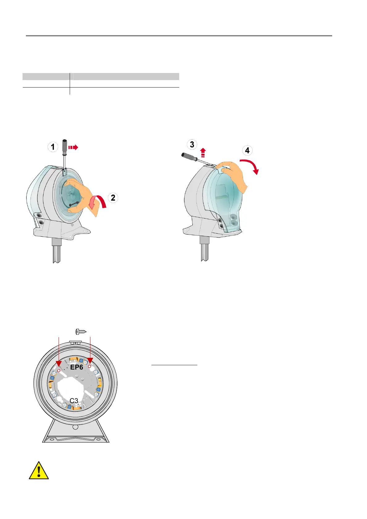
Open enclosure on the detectors side:
1. Lift plastic tab at the top carefully upwards with
a small bladed srewdriver.
2. Unfix transparent cover
by turning it anti
clockwise and remove it.
Open enclosure on the terminals side:
1. Lift plastic tab at the top carefully upwards with
a small bladed srewdriver.
2. Unfix transparent cover
and remove it .
Fig. 19: Open enclosure (Detector side) Fig. 20: Open enclosure (terminal side )
Insert detector base
Observe the required air flow direction when mounting the detector. The detector base must be mounted in the
correct positional arrangement (refer to Fig. 21)!
C3
EP6
2 x
The detector base must be fastened in the enclosure of the air duct kit
with two short screws
(see subpackage) as shown in the figure aside.
The terminal >EP6< of the base must be in the shown position (top).
Otherwise the position of the detector after engaging in the base is
not suitable for the required air inlet direction and the optimized air
flow to the inlet could not be ensured.
Fig. 21: Mounting detector base
With an incorrect arranged mounted detector base it is possible that the optimized fire alarm
capability could be not achieved due to the false air flow intake of the fire alarm detector.
 Loading...