Venturi-Air Duct Kit
FB 798349 / 04.13 33
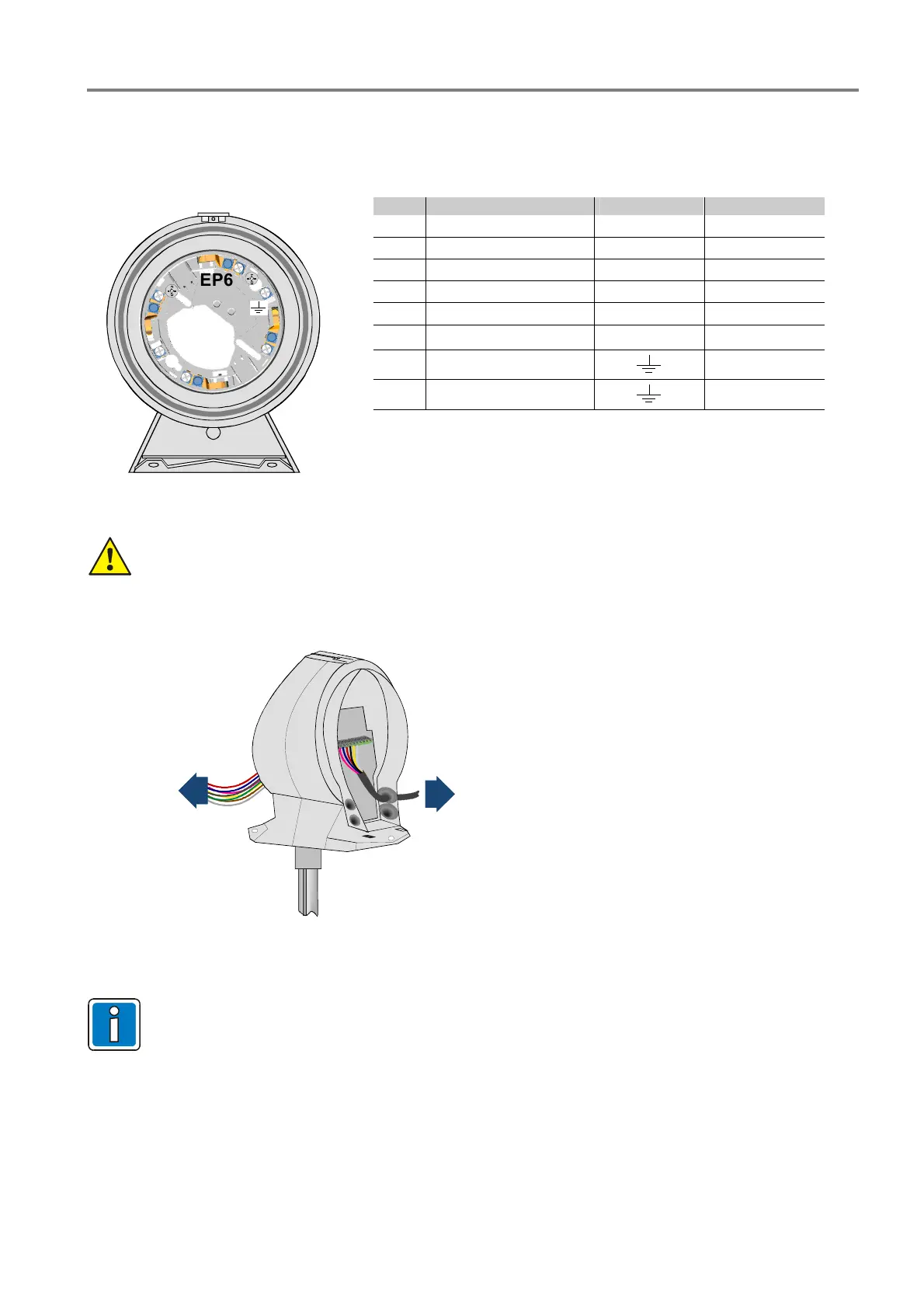
11.1 Detector base wiring
The coloured connection cable of the air duct kit must be connected to the terminals of the detector base (Part
No. 805590 or 805591) (refer to table).
No. Cable Colour Terminal Detector base
1 blue -ULin IN4
2 black -ULout OUT5
3 red +ULin C3
4 pink +ULout C3
5 yellow Ext. plus EP6*
6 green Ext. minus EM2*
7 ---
Not connected
8 ---
Not connected
EP6
OUT5
IN4
C3
EM2
1
* or Relay contact from detector base (Part No. 805591)
Fig. 22: Connection of the detector base of the air duct kit
Use clearly identified communications cable I-Y (St) Y n x 2 x 0.8 mm or fire alarm cable!
Connection of the cable shield to the ground terminal protects the signal lines against interference.
Detector
base
esserbus
®
esserbus
®
-PLus
Fig. 23: Cable for connecting the detector base and terminal for loop wiring
The terminal assignment as well as the connection to the Fire Alarm Control Panel is detailed in the
section 16 „Wiring“.
 Loading...