Excel 800 Mounting/Dismounting Modules
17 EN1B-0375GE51 R0910
Mounting/Dismounting Modules
WARNING
Risk of electric shock or equipment damage!
► Do not touch any live parts in the cabinet.
► Disconnect the power supply before you start to install
the Excel 800 System.
More than one disconnect switch may be required to de-
energize the system.
► Do not reconnect the power supply until you have
completed the installation.
Note
The terminal socket of each pluggable I/O module can be
mounted and wired before inserting and locking the
corresponding electronic module.
87 65 4 32 1 87 65 4 32 1
87 65 4 32 1
PRESS
PRESS
PRESS
PRESS
PRESS
PRESS
1
2
3
Honeywell
AUTO
0
!
AAA
100
Honeywell
!
S1 S2
2
1
0
F
E
D
C
B
9
8
7
6
5
4
3
A
71 COM a
72 COM b
73 24V
~
74 24V 0
~
71 COM a
72 COM b
73 24V
~
74 24V 0
~
COM a
COM b
24V
~
24V 0
~
21
22
23
14 4424 5434 64 25
13
12
11
31
32
33
41
42
43
51
52
53
61
62
61
62
6363
12
3
4
5678
Honeywell
AUTO
0
!
AAAAA
A
100
S1 S2
2
1
0
F
E
D
C
B
9
8
7
6
5
4
3
A
21
9
GND GN D
AI/AOV
AUX
10 11 12 13 14 15 16 17 18 25 26
22 12345678
12
3
4
56
Honeywell
--1
--0
--AUTO
!
S1 S2
2
1
0
F
E
D
C
B
9
8
7
6
5
4
3
A
21
22
23
14 4424 5434 64 25
13
12
11
31
32
33
41
42
43
51
52
53
61
62
61
62
6363
1:ABCDFERTAQWESDERT1
2:ABCDFERTAQWESDERT2
3:ABCDFERTAQWESDERT3
4:ABCDFERTAQWESDERT4
5:ABCDFERTAQWESDERT5
6:ABCDFERTAQWESDERT6
7:ABCDFERTAQWESDERT7
8:ABCDFERTAQWESDERT8
1:ABCDFERTAQWESDERT1
2:ABCDFERTAQWESDERT2
3:ABCDFERTAQWESDERT3
4:ABCDFERTAQWESDERT4
5:ABCDFERTAQWESDERT5
6:ABCDFERTAQWESDERT6
7:ABCDFERTAQWESDERT7
8:ABCDFERTAQWESDERT8
12
3
4
5678
Honeywell
!
21
9
GND GN D
AI/AOV
AUX
10 11 12 13 14 15 16 17 18 25 26
22 12345678
GND
BI
13 14 15 16 17 18 19 20 21 22 23 24 25 26
123456789101112
1 2
3
4
5 6 7 8 9 10
11 12
Honeywell
!
LON
LON
C-Bus
in
C-Bus
S1 S2
Modem
I/O Bus
Rx Tx
Power/
Alarm
C-Bus
out
C-BUS RESET
PC/HMI
13 396
14 410 7
12 285
9.6k all
Panel
LON
mid
end
76k
76k
11 1
1 2
4
5
3
6
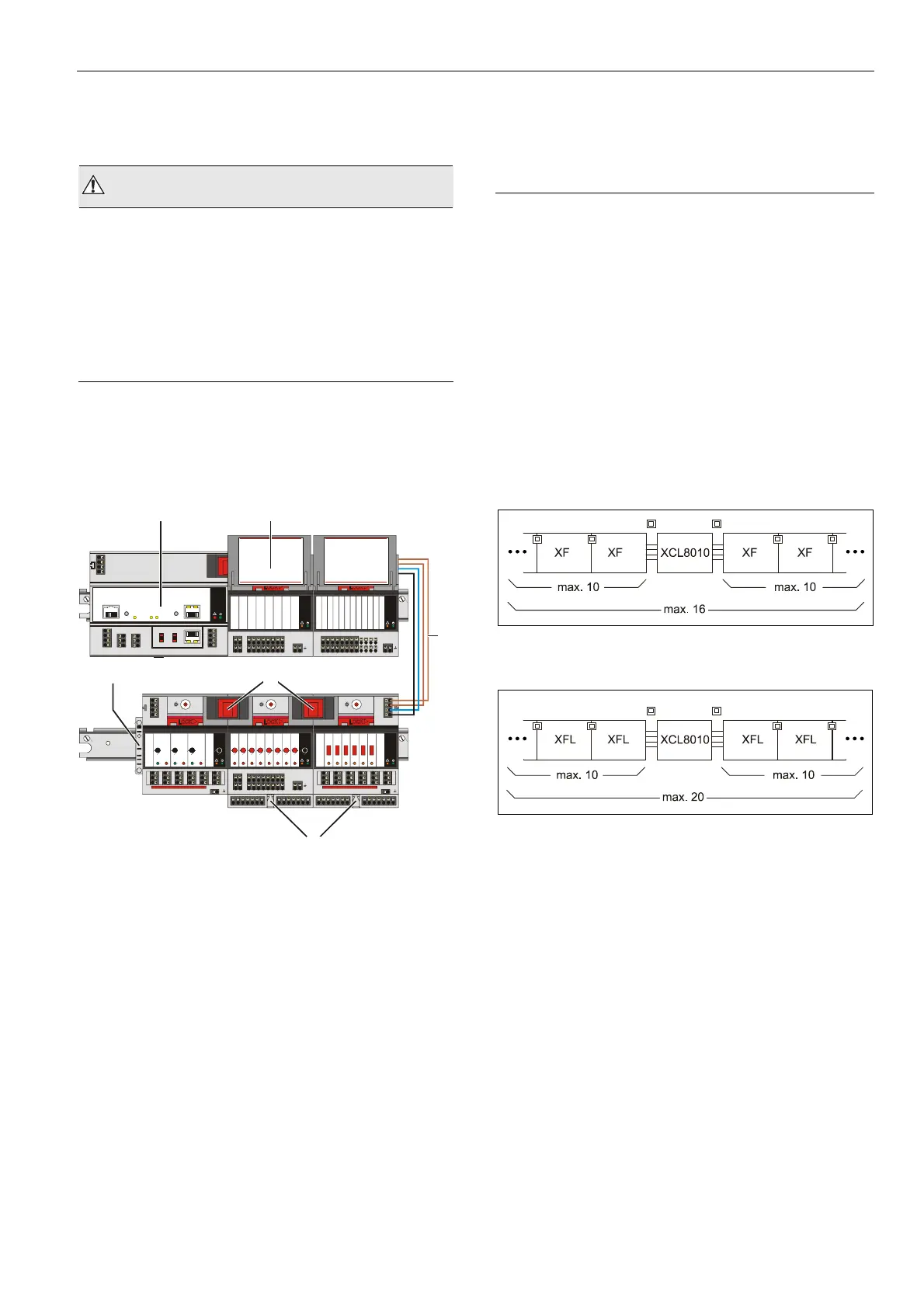
Fig. 14 XCL8010
Controller Module and I/O modules
mounted on multiple DIN rails
Legend
1 XCL8010 Controller Module
2 Swivel label holder
3 Cable connection
4 Stopper (from 3
rd
-party supplier)
5 Bridge connectors
6 Auxiliary terminal packages
Mounting/Dismounting Controller/Sockets
Mounting Sockets
Notes
When using both Panel Bus and LONWORKS Bus I/O
modules in an Excel 800 System, group both Panel Bus
modules (light-gray) and LONWORKS Bus I/O modules
(dark-gray), e.g., on different rails.
Up to 10 Panel Bus I/O modules can be mounted to one
side of the controller. In total, up to 16 Panel Bus
I/O modules can be mounted to one controller.
The XCL8010 Controller Module and the mixed Panel
Bus I/O modules are mounted on the DIN rail in the same
way as a terminal socket.
Fig. 15 Max. number of Panel Bus I/O modules
Fig. 16 Max. number of L
ONWORKS Bus I/O modules with
power supply via XCL8010
 Loading...